STV Valve Always Stay Current With Industry Trends And Refresh Industry News Related To Industrial Valves,  For Customers To Read

,

An Overview of Butterfly Valves

Butterfly valves belong to the family of quarter-turn rotational valves, created and first used in steam engine prototypes as early as the 18th century. Use of butterfly valves grew in the 1950s for applications in the oil and gas market, and 70 years later they continue to be widely used in numerous industrial applications.

Butterfly valves can be assembled with handles, manual gears, pneumatic or hydraulic actuation. The valve configuration consists of a stem and disc that rotate 90° from open to close in the clockwise direction. Butterfly valves are popular in many applications as they are cost effective to maintain, offer fast operation and are lightweight compared to other types of valves. Most butterfly valves use the same basic configuration, with a body, stem, disc, seat and stem seal; however, other parts may vary between the different butterfly valve types, such as resilient seated, lined, single offset, double offset (often referred to as high performance) and triple offset. These types are differentiated by the geometry of the disc, stem, seat and the material of the seating designs.

A key advantage of selecting a butterfly valve is the reduction of space and weight to a system compared with other options such as ball, check, globe or gate valves. Compared to a gate valve, installation of butterfly valves is less difficult from size and weight, and compared to ball valves, the cost to replace or repair is usually less. Butterfly valves are limited based on their application as they have an obstructed port, as part of the disc always faces the flow even when fully opened and they are not typically utilized in heavy slurry applications as a knife gate or severe service ball valve is preferred. Butterfly valves are also versatile products that can be used in both isolation and light control/throttling services.
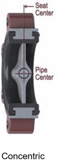
RESILIENT SEATED CONCENTRIC

Resilient seated valves are concentric with the pipeline, as the disc is held in the center of the valve. This valve type is position seated, with continuous disc-to-seat interference. Ratings are commonly in cold working pressure (CWP) rather than class rating but fit between ASME Class 125 and Class 150 flanges. Resilient seated valves are often designed below ASME pressure class ratings, thus more cost effective for low pressure applications. Stem sealing consists of a primary seal (seat flat to disc hub), secondary seal (stem diameter larger than a hole in seat) and tertiary seal (upper stem seal).
Typical body materials include ductile iron, cast iron, carbon steel, aluminum, stainless steel and aluminum bronze. Typical seat materials include EPDM, Buna-N, PTFE, natural rubber and more. Resilient seated butterfly valves are mostly used for isolation and control applications including HVAC, chemical and petrochemical, food and beverage, power generation, water and wastewater, oil and gas, mining and dry bulk handling. They are selected based on compatibility with the media running through the pipeline and flow conditions.

POLYMER-LINED CONCENTRIC

Lined butterfly valves are also concentric with the pipeline and designed to be utilized with harsh chemical media: These polymer-lined products offer longer life in media with higher levels of acids. Options include PTFE-lined and PFA-lined valves, both used in the petrochemical, food and beverage industry with corrosive media. One of the main differences between the liners is that in steam engine prototypes PFA liners remain flexible in contrast to PTFE liners over time based on the way they are manufactured. PFA is melted and chemically bonded while PTFE is sintered. Melting and chemically bonding creates a denser material and minimizes air pockets, resulting in flexibility and tight shutoff over long-term use for harsher chemical applications. The PTFE lined butterfly valve is typically used in water, brine, pulp stock and weak acid applications. The disc material can also vary based on application, between stainless steel, or lined stainless steel with PTFE, PFA and UHMWPE (ultra-high molecular weight polyethylene).

HIGH PERFORMANCE

High performance butterfly valves (also called double offset) have two offsets: The first offset of stem is off center to or behind the disc seating face, followed by the second offset, which shifts the stem off centerline of the pipeline. This double offset creates camming action, moving the disc away from the seat rather than across it, reducing rubbing between the disc and seat as seen in concentric and single offset valves.
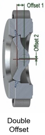
The double offset is commonly used for isolation and control applications, as well as higher cycle applications when compared to a concentric design. Most applications are made for higher temperature and pressure than resilient-seated valves. The seats are designed to provide reaction force (contact stress) to disc when in the closed position. This contact stress creates the seal with the disc edge. These designs can be pressure dependent, while others use interference fit provided by a seat energizer for that pressure range. Common body materials include carbon steel, stainless steel and aluminum bronze. Common seat materials include PTFE, reinforced PTFE, TFM, UHMWPE and Inconel.

Additional seat designs for specific application can also include fully metal seated and fire safe (both soft and metal seat). The metal seated design can withstand higher temperature capabilities up to 900°F in dirty service, abrasive service and control applications with hot and dirty service. The fire-safe seated design is used in services at risk for fire, using a soft seated material for isolation while still providing a constant metal-to-metal backup seal to the disc in the event of a fire. The intent of the valve design in these applications is to provide isolation to prevent feeding the flames.

The double offset design can be configured for cryogenic applications; they are most often used in industrial gas applications such as argon, helium, hydrogen, nitrogen and oxygen. The choice of materials is based on the service, focusing on toughness and impact strength of the pressure boundary materials at process temperature. The standards for these applications include strict material specifications along with cleaning requirements for safety and operation of the valves while in service.

TRIPLE OFFSET

Triple offset valves share the first and second offset concept with high performance butterfly valves and include an additional third offset, with the seating surfaces using an inclined conical surface. This third offset enables the sealing element (seal ring) to only engage the seating surface in the final
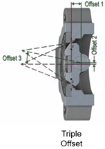
degree of closing (and immediately disengaging from the valve seat upon opening) resulting in no rubbing between the sealing components. This valve type is torque-seated, meaning torque is applied to load the sealing elements and provide the shutoff performance. The seal ring can either be laminated layers of metal and graphite or a solid metal sheet, both of which are field replaceable. The valve seat can either be bolted in (field replaceable) or integral to the valve body. Triple offset valves are inherently fire safe and applicable to pressure classes from Class 150 up to Class 1500. This design can be used in a broad temperature range of -320°F to 1,500°F in varying configurations due to the metal-to-metal sealing.

Common body materials include carbon steel, stainless steel and aluminum bronze while common seat materials include 316 stainless steel hard-faced, nickel aluminum bronze, Stellite and duplex stainless steel. Common seal materials include laminated duplex stainless, Monel, XM-19 or Inconel metal layers with either graphite or PTFE, and solid metal options include duplex stainless steel, Inconel or XM-19. Main applications for the triple offset valves include steam-distribution, petrochemicals, tank farms, terminals, and switching.

The triple offset valve configured for cryogenic service, allow for temperature as low as -420°F; it is used in LNG, liquid hydrogen and liquid oxygen service, to name a few. Extended bonnets keep the stem packing from the extreme cold temperatures.

The higher temperature designs, up to 1,500°F, use a solid seal ring and a bonnet to dissipate heat transfer to the packing and actuation. This design is mostly used in turbines, molten salt and hot air applications.

END CONNECTION TYPES

Butterfly valves have multiple options for end connection types, including wafer (flangeless), lug, double flanged and buttweld end. Some options allow for ease of maintenance, some are suited for dead-end service and some designs have weight and cost reduction implications compared to each other.

  • Wafer valves are designed to be installed between flanges, with a short face-to-face dimension in relation to the pipeline diameter. These valves cannot be used for dead-end service, which requires additional isolation valves when shut down for maintenance. Wafer options are lighter and cheaper than lug style and often used in lower pressure applications.
  • Lug valves are designed to be bolted to one or both flanges using fasteners threaded into lug protrusions on the valve body, with a short face-to-face dimension in relation to the pipeline diameter. These valves can also be used in dead-end service depending on seat design but may be de-rated and can be heavier than wafer style.
  • Double flanged valves are designed with flanges on both ends of the body to secure the valve to mating flanges on the pipe with bolts or studs and nuts. They can be used in dead-end service; however, some valve types may be de-rated.
  • Buttweld end valves are designed with bevels (weld preparation) on each face to match thickness and bevel on the pipe. The two ends are butted to the pipeline and welded, used in applications where dismantling is not common, or a potential leak path between flange bolting is a concern.

AUTOMATION TYPES

Many types of actuators can control the opening and closing characteristics of a butterfly valve. The actuator provides the torque required to properly open and close the valve during service. The following types of actuators are paired with butterfly valves:

butterfly valves:

  • Manual valve operation is the simplest form of actuation. It uses a wheel or lever to control the position of the stem and disc. Manual operators are also very inexpensive and typically are used with smaller sized valves that have a lower torque requirement. These are especially suitable in applications where power is not present to operate the valve. The speed of manual operators is somewhat slow, so they would not be used in emergency shut-off applications.
  • Electric valve actuators contain a gearbox that can adjust motor speed, raising or lowering the torque. The electric actuators are easy to maintain, are relatively simple to install and are fairly quiet during operation. The position of the valve is based on the voltage or current signal input and can contain limit switches that stop the actuator when fully closed or fully open. Electric actuators are used where there is a stable power supply.
  • Rack and pinion actuators contain springs within a chamber that operate from the entry and exit of compressed air. These types of pneumatic actuators can be single or double acting, are compact in design, relatively inexpensive and lightweight. They have quicker reaction times, allowing for their use in throttling services; they need an external supply of compressed air.
  • Scotch yoke actuators can be operated with compressed air or with hydraulic fluid. These consist of a crank and piston in a hollow cylinder. Pressure is applied to one side, and the resulting force moves the piston linearly to rotate the stem and disc. These actuators can be designed with modules for ease of maintenance by just removing one section of the actuator instead of the entire assembly. The scotch yoke is larger and more costly than the rack and pinion, but output creates much higher torque for larger sized valves. The scotch yoke also can be paired with control accessories for use in quick acting or soft closing applications.
  • Hydraulic valve actuators use hydraulic force supplied by a fluid to control the position of the disc and stem. They are available in either single or double acting. Single acting works by the absence of fluid pressure, keeping the valve in the closed position; as pressure builds up, the fluid pushes the piston towards the valve to open. The double-acting type contains a hydraulic pump that changes the direction of the fluid to open and close the valve. These actuators are used for the very large or heavy-duty valves that require a large torque to operate; they also can be used with solenoids to better control position.

BUTTERFLY VALVE DESIGN STANDARDS

Butterfly valves have many national and international standards that dictate the design criteria, such as wall thickness, face-to-face length, mounting patterns, flange drilling, fugitive emission and more. Below are some of the common standards for the many types of butterfly valve designs.

Common Standards for Valve Design


Butterfly valves offer a unique value proposition based on their weight, footprint, and cost effectiveness.  They provide a variety of options from seat material, sealing designs, and range of temperature and pressure ratings.  Butterfly valves offer one of the largest valve markets behind ball and gate valves.  They continue to grow based on the flexibility of automation, lower torque and improved fugitive emissions performance compared to linear valves.


,

How long does a cast steel gate valve last?

How long does a cast steel gate valve last?

How many years is the service life of cast steel gate valve? Generally, at normal temperature, the medium is water and there is no high-strength hydraulic impact. Most cast steel gate valves can be used for 3 years and 5 years. The contract signed between the manufacturer and the customer states that the warranty period is one year, so it is necessary to eliminate the situation that the customer changes the working conditions at will. Cast steel gate valve can be used under the working condition of about 300 degrees

Generally, at normal temperature, the medium is water and there is no high-strength hydraulic impact. Most cast steel gate valves can be used for 3 years and 5 years. The contract signed between the manufacturer and the customer states that the warranty period is one year, so it is necessary to eliminate the situation that the customer changes the working conditions at will.
Can cast steel gate valve be used under the working condition of about 300 degrees?


The abrasion resistance of the first-class valve is 2000 times, while that of the first-class valve is 4000 times. The service life of gate valves varies from country to country. It is stipulated to be 30 ~ 40 years in Japan, while it is stipulated to be 40 years in the United States and France.
working principle
Most gate valves are forced sealed, that is, when the valve is closed, the gate shall be forced to the valve seat by external force to ensure the tightness of the sealing surface. The gate of the gate valve moves in a straight line with the valve stem, which is also called rising stem gate valve. Generally, there are trapezoidal threads on the lifting rod. Through the nut at the top of the valve and the guide groove on the valve body, the rotary motion is changed into linear motion, that is, the operating torque is changed into operating thrust.
purpose
1. The gate valve is only used to fully open and close the medium on various pipelines or equipment, and is not allowed to be used for throttling.
2. For the gate valve with hand wheel or handle, the auxiliary lever shall not be added during operation (if the seal is not tight, the sealing surface or other parts shall be inspected and repaired). Turn the hand wheel and handle clockwise to close, otherwise it will open. The gate valve with transmission mechanism shall be used according to the provisions of the product operation manual.

1.How long do valves last shut?

You can expect a shut-off valve to last about 10 to 25 years, with an average of 20 years. But, if they are not “exercised” every year or two, there is good chance a valve will be freeze prematurely in the open position just when you really need it to close for a plumbing emergency or repair.
2.When should a gate valve be replaced?
These problems are typically caused by mineral buildup, so you should fully close and open your gate valves every few months to clear potential problems. If your gate valve has severe pitting or corrosion, you will need to replace it.
3.How do you fix a gate valve that doesn’t close?

he first step if a gate valve will not close completely

If the handle of the valve does not turn freely then loosen the packing nut just above the valve body and around the stem of the valve. Loosening it just one turn should be fine – just remember to tighten it back up when you are done.

,

BALL VALVE INSTALLATION & MAINTENANCE

Ball valves of all materials and seat types are easy to use and long lasting if installed and maintained correctly.

valve-installation-maintenance-ball-valves

Ball valves of all materials and seat types are easy to use and long lasting if installed and maintained correctly.

Storage Conditions

  • To protect the seat and seals, do not unpack the valves until they are ready for installation. By doing this you are protecting the valve from dust and debris which may eventually cause seat leakage.
  • Keep in a cool well ventilated space if storing for a longer period of time. For cast steel valves (Black finish) the body may require additional application of oil to prevent corrosion.

Valve Installation

  • Ball valves can be installed in any orientation. However in bigger sizes to reduce load on the valve caused by the actuator or gearbox trying to pull away it may be necessary to install with the drive shaft vertical. Electric actuators usually require vertical installation.
  • Verify the material of the ball valve body, seat and ball before installation. Ensure that there are no defects caused by storage or transportation.
  • Verify the pressure rating of the valve vs the application requirement.
  • Verify the temperature rating of the valve vs the application requirement.
  • Verify the valve thread (BSP, NPT, socket weld ANSI), flange (ANSI 150, ANSI 300 etc) or solvent weld (BLP schedule 40) vs the application requirement.
  • Complete all welding works before valve installation and be sure the flange has cooled to ambient  temperature before installing the ball valve.
  • Make sure there is no welding residue, waste, rust or other debris in the pipe before installation. Wash with water or a mild detergent if needed.
  • Clean the surface of the flange or pipe thread that will come in contact with the ball valve to ensure it is free of rust and debris. Wash with water or a mild detergent if needed.
  • Make sure there is no warpage of the flange or misalignment of the ball valve in relation to the flange.
  • Support the valve where necessary to reduce load on the piping (important on bigger valve and actuator assemblies).
  • For 2 way and 3way threaded valves (BVS, BVF8, BLS3) it will be necessary in metal pipework to allow for removal of the valve for maintenance by having a pipe union installed. 3 piece threaded and 2 piece flanged ball valves can be removed for maintenance without disturbing the pipework.
  • Tighten the bolts on a flanged valve one at a time doing it in stages so even pressure is applied and a seal is formed between the valve and flanges.
  • Once the installation is complete, operate the valve several times to ensure it is free from impingement and rotating through its full 90 degree operation.

Field Testing

  • Ball valves are designed to hold rated pressures only. Test pressures above rated working pressure in the closed position can cause damage to the valve.
  • With the ball in the open position the pipeline can be tested up to the valve hydrostatic test pressure.
  • Seat leakage can occur with foreign material between the seat and ball. If this occurs, open the valve 10 to 15 degrees to obtain high velocity flushing action. Close and repeat if necessary.
  • Seat leakage can result from a rotational shift in position of the ball in relation to the body. Readjust the closing stop on the actuator/gearbox as necessary.

Operation

  • Do not use the valve at pressures above its working pressure.
  • If the valve is jammed in a position between open and closed check the actuator operation. If necessary remove the actuator and manually operate the valve to fault find. Remove and check valves for foreign objects if required (see maintenance).
  • Excessive torque from the actuator can damage the internal valve parts.

Maintenance

  • Cycle the valve once a month or more if it is not used regularly.
  • Relieve the system pressure before maintaining the valve.
  • To remove from pipework reverse the installation sequence.
  • Replace valve seats and seals by removing the end plates. With the ball in the closed position press carefully push out the end seats and the ball. Avoid damage to the polished ball surface using a soft clean cloth to hold. Push the drive stem up from inside the cavity to expose the stem seals. Reinstall the seals, stem, ball, seats and end plates. Use only approved lubrication on the seals. Test and refit into line as in installation sequence.
  • For operational instructions please see each video link under products.

Design Guidance & Product Advantages

  • When sizing the valve always consider available space for the actuator and feedback devices.
  • Consider valve supports to carry excess loads.
  • Extension shafts in SS316 are available upon request. This allows the valve to be buried in pits and actuators to be above ground.
,

What is valve Casting?

Casting does one of the earliest production methods use by many industrial organizations in the history of art and design. However, their uses and applications have a long and varied history, and they continue to play an important role in today’s artistic and industrial production areas. Casting is a quick and inexpensive way to give a metal (or other material) object the shape you want. The metal shapes created by the casting process may be complex designs that would otherwise involve a significant technological investment if done in any other way. Read this guide to learn more about casting, its types, advantages, and disadvantages. First, let’s have a look at what casting is.

Metal Pouring

What is valve Casting?

“Valve Casting is a manufacturing technique. In the casting process, a liquid material is added into a mold to get the desired item. The mold has a hollow space of the required shape. The liquid material in the mold is allowed to solidify. This solid part is called a “casting.” The liquid material present in the mold in solid form is ejected or broken out of the mold to finish the process.”.

Types Of Casting

3D Printing Investment Casting

Sand Casting

This casting procedure uses a sand mold to create castings .”Sand casting can use to produce steel, iron, and most nonferrous alloys. The most common casting method, sand casting, uses disposable sand casting molds (The mold in sand casting is made up of Sand) to create intricate metal pieces in almost any alloy. However, sand casting has a poor production rate.

This is because to get the product; you must destroy the mold. Therefore, this method has a disadvantage compared to other methods in which the molds are reusable. The sand casting technique involves using a furnace, metal, design, and sand casting mold. First, the metal is heated in the furnace and poured into a sand casting mold. The solidified casting can be removed once the sand mold separates along a dividing line.

Foundry Mean

Die Casting

“To make a casting, a high-pressure metal liquid is forced into a precision metal mold cavity at fast speed, then cooled and solidified under pressure.”

Die casting is a production process. The molds used in this process are not wasted. They are reusable molds. These reusable molds are called dies. The die casting manufacturing process does use to make geometrically complex metal objects. A furnace, metal, mold(the mold in Die casting is made up of metal), die casting machine, and die are all used in the die casting process. Like sand casting, the metal does the heat in a furnace. Then, it does force into a die casting mold (dies). The metal heated in the furnace does aluminum or zinc (nonferrous). The molten metal feeds into the dies, where it cools quickly and hardens into the completed item, referred to as the casting.

Die casting molds consist of two halves with a cavity

The molten liquid melt is forced into this cavity during the casting process. The halves are mounted on a fixed and movable machine surface. The mold halves are subjected to a great deal of pressure throughout the casting process, which is why locks are included. Furthermore, specific areas of the die casting mold are cooled and/or heated in order for the casting to solidify as required.

Die Casting manufacturers are of two types:

  1. Hot Chambers Manufacturers –  These manufacturers can use alloys with low melting temperatures, for example, zinc.
  2. Cold Chambers Manufacturers can use alloys with high melting temperatures, for example, aluminum.
investment casting vs sand casting

Investment Casting

“Thousands of years ago, molten metal does pour into a disposable ceramic mold in a method known as investment casting .” In the modern age, there are many investment casting foundries where the investment casting process occurs. First, a wax pattern – a disposable component shaped like the intended part – can use to create the mold for investment casting.

After the pattern does melt into the mold, it can cover in a ceramic slurry. This “invests” in the design. Investment casting is also known as “lost-wax cast” because the wax pattern can remove from the mold. The lox-wax process is one-to-one, meaning that one pattern makes one item. This increases manufacturing time and costs. Because the mold does destroy during the manufacturing process, parts with intricate geometries or fine details can still make.

types of patterns in casting

Shell Mold Casting

“Shell mold casting is a metal casting sand process. In this casting process, molten metal is poured into a disposable mold of the desired shape”.
In shell mold casting, on the other hand, the mold is a thin-walled shell made by depositing a sand-resin mixture around a design. Multiple shell molds are made from the pattern, which is a metal piece shaped like the desired part. Higher manufacturing speeds are possible with a reusable pattern, whereas complex geometries are possible with disposable molds. A metal pattern, an oven, a sand-resin combination, a dump box, and molten metal are required for shell mold casting.

casting

Centrifugal Casting

“ It is a permanent mold procedure that fills a mold with molten material using centrifugal force.” This casting method is of three kinds.

  1. Centrifugal Casting
  2. True centrifugal casting
  3. Semi centrifugal casting

Their mechanism of the process is the same. Molten metal is poured into a bowl, from which it is centrifugally driven into the mold( rotating around an axis). The centrifugal force is the radially directed outward force on an object moving in a curved path. Alfred Krupp developed the centrifugal casting process in 1852. He used centrifugal casting for making railway wheels. By carefully controlling the metal and crystal structure, high-quality items can be produced utilizing this casting technique. These casting techniques are primarily employed to create rotationally symmetric items. This procedure does not produce the finished result; it takes some machining to achieve a fine finish.

Treatment of steel casting defects

Permanent Mold Casting

Permanent mold casting is a metal casting method. In this method, the mold can fill with molten metal and remains close until it cools and hardens into the desired shape. Permanent mold casting is similar to sand casting. Sand casting, on the other hand, uses a disposable mold that is thrown away after each cycle. Like die casting, permanent molds use metal molds (dies) that can be reused thousands of times and usually consist of steel or cast iron. In permanent molds, casting can also refer to as gravity die casting, in which case there is no external force to pour the molten metal into the mold.

Permanent mold casting does most often use to make small base metal parts with consistent wall thickness in large quantities. Alloys of aluminum, copper, and magnesium are the common non-ferrous metals used in this procedure. However, it can also use graphite molds to cast iron and steel.

Advantages Of Casting

Following are the advantages of castings which make it best among most manufacturing processes.

  1. Casting makes the item have extremely intricate form and internal hollows.
  2. It can use to create parts ranging in size from a few hundred kilos to a few kilograms (thousand of kilograms).
  3. Both non-ferrous and ferrous metallic elements do cast.
  4. It is cost-effective and waste-free since the excess metal from each casting is re-metalized and re-used.
  5. It is a process that is very adaptable to the needs of mass manufacturing, allowing for the rapid creation of vast quantities of a particular casting.
  6. Casting tools are more affordable and straightforward.
  7. Only castings can make certain metals and alloys.
  8. From casting, an exact object is created.
  9. The isotropic structure is created.
  10. Among all production methods, it is the most cost-effective.
  11. Casting can use to make composite components.

Disadvantages Of Casting

No doubt, casting is the most cost-effective method among all production methods, and exact objects can create from casting. But there are some disadvantages of this method. Following are the disadvantages of this method:

  1. Surface quality is relatively rough, requiring a wider tolerance and making mating interfaces unsuitable.
  2. Some metal casting processes have a limit in terms of size and pattern.
  3. Although additive manufacturing technologies such as binder jetting have recently been utilized to manufacture molds, patterns are time-consuming and expensive to create.
  4. Some casting processes are costly for medium runs.
  5. The size and substance of the part are determined by the casting method used. For permanent mold castings, for example, only non-ferrous metals are allowed.
  6. This method does hinder casting defects, for example, moisture in the sand.
  7. When compared to forging, it has lower fatigue strength.

Applications Of Casting

Let’s have a look at some applications of the casting process

General applications

The following are some examples of general casting applications.

  1. Parts made of cast iron are utilized at railway crossings.
  2. Transportation vehicles.
  3. Applications of atomic energy
  4. Generator of electricity
  5. Parts of railway crossings
  6. Turbine Vanes
  7. Agriculture parts
  8. Parts of communication
  9. Turbine at a power plant
  10. Parts for sanitary fittings.
  11. Engine block for a car
  12. Tool beds for machines
  13. Rolls for the mill
  14. Pipes for water and sewage.
  15. Engines for transport vehicles

Applications of Casting in the Automobile industry:

Components of complex shape and size were required in the vehicle industry. Other manufacturing methods are unable to make these pieces. Therefore, the casting process does use to make 60% of the components in an automobile. Because the strength of Casting components is greater than that of other manufacturing parts, strength is a critical attribute in automobiles.

  1. Cylinder Block
  2. Fuel Intake part
  3. Piston Ring
  4. Engine Components
  5. Parts of sunroof
  6. Transmission parts

Application of Casting in industries :

The casting technique can use to make a cylindrical hollow cylinder, a piston can use in automobiles, a pulley, engine manifolds, valves, nuts, and Defence equipment, among other products. Casting does utilize in various industries, including aerospace, Defence, automobiles, trains, construction, agricultural, mining, and chemical. It can also use to make home decor and ornaments.

  1. In transport industry: Shipping, aerospace, railways, automobile
  2. Households: Appliances, Kitchen equipment, fitting equipment
  3. Defense equipment: Vehicles, Artillery, Supporting equipment
  4. Plant equipment: Sugar mill equipment, Plastic industry, Paper industry, Thermal power plant, Petroleum industries
  5. Art object: Furniture, sculptures, idols
  6. Municipal casting: Valve, pipe, joints, and fittings
  7. Machine tools: plastics molding, forging, extrusion, and forming.

Conclusion

Valve Casting is an essential production technology that enables the manufacturing industry to make various items. Casting can do in various ways, including sand casting, die casting, investment casting, and more. We hope that this guide has given you a better understanding of the casting process and its benefits and drawbacks.

,

Top Industrial Valve Manufacturers To Consider In 2022

Top  Industrial Valve Manufacturers To Consider In 2022

The ranking of industrial valve manufacturers in China is continually rising over the past years. This is because of the increase in a lot of new Chinese suppliers in the market. These companies are catching up with the rapidly increasing demand within the country’s flourishing economy of industrial valves.

The demand for industrial valves in China has grown much larger compared to the combined demand in other countries in the world in 2006. This exceeded the capacity of international suppliers and are therefore largely served by domestic industrial valve companies. In fact, the largest industrial valve manufacturer in the world is China. You can check this article for the top valve manufacturers in China in case you are interested. 

In this article, we are going to present to you the top ten industrial valve manufacturers you should consider this 2020. These manufacturers not only have different valves, but also have high-quality strainers for sale. We have included one manufacturer located in China. We will briefly discuss each company and their offered products in the following sections.

Source: AVK

#1 AVK Group

AVK manufactures industrial monitoring and control systems for discrete and process industries. AVK’s division for flow control, known as AVK Valves, is manufacturing industrial valve varieties for the following industries:

  • Oil and gas,
  • Water treatment,
  • Paper and pulp,
  • Steel,
  • Chemical, and
  • Power generation.

The company also owns other subsidiaries engaging in valve manufacturing for specific segments of users.

Contact Now

Source: Bel Valve

#2 BEL Valves

BEL Valves is a UK-based manufacturer specializing in high integrity and high-pressure valves for oil and gas industries. The company caters to pressures reaching 16,500psi in depths of water up to 3,000 meters. 

The British company’s clients include the biggest national and international companies around the world such as ExxonMobil, Chevron, Total, Shell, BP, and Saudi Aramco. What makes them unique from other industrial valve companies is that they manufacture the products in-house separate from the raw materials.

Contact Now

Source: SLB

#3 Cameron (Schlumberger)

Cameron embarks in industrial products manufacturing including compression, processing, pressure control, and flow control systems. Aside from these, the company also offers services for aftermarket support and project consulting for oil and gas industries. Cameron is among the world’s leaders in systems for flow control. Their products include valves and automation technologies for valves that are exploited in oil and gas industries.

Contact Now

Source: Emerson

#4 Fisher Valves & Instruments (Emerson)

Fisher Valves has over 130 years of service history after it was established in the United States. The giant company, Emerson, acquired the company many years ago. It has fortified its place as the world’s largest supplier and manufacturer of control valves for oil and gas industries.

According to them, the reason why they are better than other companies is that they take the valve’s internal parts to the care of experienced engineers. Also, they believe that they have developed the most advanced controls that go with the valve. This includes control and diagnostics and very fast opening. These capabilities are crucial for the operation of a whole plant.

Contact Now

Source: Xhval

#5 XHVAL

XHVAL was founded in 1986 and is a manufacturer of industrial valves based in China. The company specializes in the manufacture of affordable industrial high-quality ball, butterfly, check, gate, plug, globe, and cast iron valves. They focus on providing high-quality service by manufacturing innovative valves intended for the chemical, oil and gas, and other industries. 

XHVAL offers a variety of industrial valves ideal for piping systems and energy service industries molded through constant innovation. In addition to this, they also provide customization of high-quality and world-class industrial valves to fit every application. This differentiates them from other competitors in the market. And to meet the global standards for industrial valves, the company gives continuous supervision and quality control to their products.

Contact Now

Source: Pentair

#6 Pentair Valves and Controls

This company is part of the bigger Tyco conglomerate, a very diverse manufacturing company. Pentair Valves and Controls, previously known as Tyco Valves and Controls, is still among the largest valve manufacturers for oil and gas industries. The company’s headquarters in the Middle East has a strategic position to serve valves for the region. They claim that they are comprised of knowledgeable and experienced technicians worldwide to provide a quality service.

In addition, they also stated that their products are manufactured and designed to work reliably and safely under extreme pressures and temperatures in the oil and gas industry.

Contact Now

Source: JC

#7 JC Valves

JC Valves is a Spanish-based manufacturer claiming to have many varieties of high technology and high-quality ball valves with competitive prices. The company does not only serve petrochemical and oil and gas industries. They also serve other industries needing valve products such as the power generation and chemical sectors.

JC Valves has a manufacturing plant that utilizes vacuum technology that essentially eliminates any impurities and gases during the phase of metal melting. This considerably enhances the product’s service life.

Contact Now

Source: Petrolvalves

#8 PetrolValves

PetrolValves is one of the leading industrial valve manufacturers established in 1964. It became a leader in the Subsea Market in the 1970s for the development of dedicated products such as:

  • Swing check valves,
  • Wedge gate valves,
  • Ball valves, and
  • Slab gate valves.

The company developed its first ball valve with a metal-to-metal sealing and opened branch offices around the world to reinforce its commercial network in the 1990s. PetrolValves’ purpose, according to them, is the safe and efficient delivery of solutions for flow control that suit the requirements of their global customers in the oil and gas industry. 

Contact Now

Source: Valvitalia

#9 Valvitalia

Valvitalia is an Italian valve manufacturer including various energy equipment. They claim to have the following which differentiates Valvitalia from its competitors.:

  • A large inventory,
  • Experienced management,
  • Performance,
  • Quality, and

Full commitment to their customer’s satisfaction.

Valvitalia currently supplies products in Oman, Qatar, United Arab Emirates, and Saudi Arabia. The company manufactures a wide variety of products including all kinds of actuators, valves, flanges, fittings, and gas equipment.

Contact Now

Walworth logo

 #10 Walworth

Walworth covers the Middle Eastern territory with ValveTech as the company’s distributor for the whole region. The company was established in 1842 and has dedicated to the design and manufacture of various fluid control valves. 

Walworth is among the world’s oldest manufacturer of valves influencing the Mexican market and offers a variety of specialized valves cast using API standard steels. 

Contact Now


Conclusion

There are hundreds of valve manufacturers and suppliers around the world. This gives you a wide array of varying options when choosing a flow control valve for your application. With the continuous rise of new industrial valve manufacturers, these companies are pressured to keep the production of valves with very high standards. This makes choosing the right valve manufacturer for your needs more challenging.

Speaking of, this article discusses the basics of industrial valve selection in case you are interested. That’s it! Hopefully, this article has helped you choose your ideal valve manufacturer.


,

What is the different Y strainer and Basket Strainer?

Basket strainers are a device typically connected to a pumps suction, which is used to filter out solids or debris larger than the mesh contained within the strainer, which would otherwise damage the pump, internal parts or system. They are used to capture particles which are usually visible to the naked eye, and if smaller, filters are typically used.


Strainer Vs Filter
Used to capture larger   solids visible to naked eye Used to capture   particles invisible to naked eye <40 microns which may include salts, or carbon   particles
Designed for a single   type of fluid Can capture   different fluids such as water within oil
Lower pressure drop   enabling use of low pressure designs of pumps Require high   pressure pumping involving high powered positive displacement or multistage pumps   which if selected incorrectly will experience rapid wear by the handling of   such particles
Filter mesh is designed   to be reused over many years Can be single use or   reused through the use of backwashing


Working Principle of Strainers

What is a Basket Strainer

Basket strainers are a device typically connected to a pumps suction, which is used to filter out solids or debris larger than the mesh contained within the strainer, which would otherwise damage the pump, internal parts or system. They are used to capture particles which are usually visible to the naked eye, and if smaller, filters are typically used.

Designs consist of a suction inlet, discharge outlet, bolted top cover and casing. The casing holds a filter typically manufactured from wire mesh designed to filter solids which become trapped by the mesh, and sink within the casing. Top covers can be clear or solid. Housings may have a drain at the bottom of the casing where solids will sink to enable them to be drained away.

Basket Strainer Designs

There are various designs known as Y Type, Simplex, Duplex or Backwash.

what is a Y STRAINER

What is a Y Type Strainer?

This type of design is the most economical type which can be mounted horizontally or vertically and is compact in design. Other designs can typically only work horizontally.

They are cast in one piece, meaning they usually have a higher pressure rating tolerance. However due to their design, they produce a larger pressure drop than other variants. 

What is a Simplex Strainer? 

Simplex models are designed for larger pipework, are longer and wider in design containing a significantly larger basket with removable lid for ease of maintenance.

Due to the larger surface area they are designed for capturing larger amounts of solids, and produce lower pressure drops. They can only be installed horizontally, but are easy to inspect and maintain without drainage of pipework. 

What is a Duplex Strainer? 

Duplex models are very similar to simplex strainers in design, however contain two filter baskets which can operate simultaneously or separately. Having twin filters ensures processes can run interrupted whilst they are maintained, as one can continue to function, while the other is maintained. 


Self Cleaning Strainer/Backwash / Automatic Strainer Design 

Self cleaning strainers, also known as backwash filters or automatic strainers consist of a strainer, drain, scraper and motor.

Within the strainer there is a hollow shaft with a blade which when the cleaning process is initiated, scrapes along the inside of the mesh removing debris. Simultaneously a bottom outlet valve opens creating an area of low pressure causing the recently freed debris to flow via the bottom outlet valve and be drained away.

The cleaning process is initiated either by a timer, which starts the motor located at the top of the unit to begin the screening process or via a differential pressure switch which senses when the screen is blocked.

Pressure switches are located on the inlet and outlet of the unit and when the inlet pressure is higher than the outlet pressure, the filter is known to be blocked.

These are low maintenance designs enabling the mesh to remain clean and free from solids with long maintenance intervals, without manual

Duplex Strainer Exploded View

Strainer Design Comparison Table – Basket Simplex strainer vs Duplex vs Y Type

Y Type

  Advantages

Simplex Strainer

  Advantages

Duplex Strainer

  Advantages

Backwash / Auto cleaning

  Advantages

Mounted Horizontally   or Vertically Maintain without   draining pipework Mesh can be cleaned   without Process Stoppage Autonomous self-cleaning
Compact in design Lower Pressure Drop Redundancy / Spare   Capacity in Design Zero process   stoppage
Economical Higher Solids   Capture
Disadvantages
During Cleaning as   the strainer is at the lowest point, there is a larger loss of fluid and   system may need to be drained Process must be   stopped during cleaning Bulkier in Design Large units   requiring piping to drain, which may require secondary filtration or dewatering


Higher Pressure Loss Only Work   Horizontally Only Work   Horizontally Higher Initial   Outlay

Pressure Loss

Below is a graph indicating single and double Basket strainer Pressure drop compared with Y type designs:


At a flow of 10M³H, (166L/min) the pressure drop on the basket type is only 0.3 bar, compared with 0.4bar (40KPA) for a 1″ (DN25) Type


,

Difference Between Gate Valve And Globe Valve

Gate valves and globe valves are two of the most common valves used in industrial applications. Both contribute greatly to any industrial services. They may look alike but these valves function differently.  In this article, you will know what makes the gate and globe individually unique as well as the major differences between the two valves.

Gate Valve

Gate valves are linear valves belonging to the shutoff valve family. Characterized by its wedge-like disc, the gate valve is commonly used for isolating media because of can tightly seal off media. This kind of valve can be used in applications where tight sealing is required. A special kind of gate valve, knife gate valve, is used in thicker and more viscous media.

Gate valves provide little pressure drops since no obstruction comes in the way of media flow. The gate operates by the gate disc moving upwards to open the valve. It closes by moving the disc downwards to meet with the seats. The disc of the gate valve can be formed like a wedge, knife or parallel.

While it does have some throttling capacity, the gate valve is not used to regulate the flow of media. Its disc is thin so the vibration from the media causes this thin disc to misalign from its seat. This condition causes damage and shortens its service life. To lengthen the valve life, the gate valve should fully open or fully close when in use.

Globe Valve 

The globe valve is also a member of the linear motion valve family. Its functions include stopping and starting of media as well as regulate the flow of media. Because of its design, the globe valve provides a tight seal with fewer chances of leakage.

The globe valve is aptly named as such because of its traditional body design similar to that of the globe. But as one gate valve China manufacturer would tell you, however, modern globe valves may adapt to other body shapes. A plug-like disc allows or prohibits the flow of media.

The seats of the gate valve are parallel to the flow of the media so there is less seat erosion when the valve is on. This also makes the globe valve a great throttling valve. The downside is, there is a high-pressure drop because of its design. 


If you look at the image above, you’d notice that the valve forces the media to change its flow direction exactly inside the valve. Additionally, the media flow inside the valve depends on the space between the seat and the disc. The farther these are, the more fluid comes in.

Globe valves highly suitable for applications where safety and leaks are the main concerns. These valves are often in top-entry design, meaning, access to the internal components of the valve is from the top.

Gate Valve vs. Globe Valve

There is always a comparison between the gate valve and the globe valve. Members of the linear valve family, you’d find these two in tandem in pipe systems. How would you use these two? Look at the differences between the two below:

  • Structure

One of the main differences between the gate valve and the globe valve is how these look. The gate valve construction is much simpler. Much of its internal components are located on the top part of the valve body. When it is turned on, its body becomes hollow. That’s why there is a little pressure drop. The gate valve may have a rising or a non-rising stem.

On the contrary, many globe valve parts are inside the cavity itself. Since its primary purpose is to throttle and provide positive shut-off, the design allows obstructions that aid the globe valve in this purpose. The design also permits changes in flow direction and rate that contributes to a high-pressure drop. The globe has a rising stem.

  • Applications

The gate valve is suitable for applications where low-pressure drops are of utmost importance. It’s a multidirectional valve. The globe is best used in applications where massive changes in pressure are not an issue. This valve is unidirectional.

  • Function

The gate valve is not designed for flow control; it is for isolation of media. The gate valve cannot handle the strength of the media flowing in a partially opened position. On the other hand, the globe valve is more of a control valve.

  • How They Work

In the gate valve working mechanism, the disc lodges between the seats. Its movement is at the right angle in relation to the media flow. It provides either full flow or no flow at all. If you open the valve, the flow space is as big as the valve cavity with little extra where the stem and the seats are located as you’d notice in the first image.

                                                               Source: https://www.quora.com

Conclusion

A fascinating facet of valves is that they may look the same but they can function quite differently. This remains true in the case of gate and globe valves. If you are seeking an industrial valve supplier, you can choose manufacturers in the china,  Or you can also get the great manufacturers in this complete valve manufacturers guide in China.


,

Top 7 Valve Supplier In Malaysia

Valve manufacturers in Asia are on the rise in rankings. In recent years, several new Valve manufacturers in Malaysia have entered the market. They fulfill the increasing demand for industrial valves in the rising economy of that region. Some of the top players are:


Top Ball Valve Supplier In Malaysia

A ball valve is a quarter-turn valve that regulates the flow of a hollow, perforated, and pivoting ball. When the hole is in contact with the flow, it is opened and closed when the valve handles a pivot of 90 degrees. When opened, the handle is straight and perpendicular to the flow and closed, making it easy to verify the state of the valve.

MIR Valve Sdn. Bhd, Kuala Lumpur, Malaysia.

Established: 2008

Website: http://www.mirvalve.com/

Valve Types: Floating & Trunnion Mounted Ball, Two Way, Three-Way Ball Valve.

Certification: ISO 9001, ISO 14001, ISO 45001, CE-PED, IEC 61508, etc.

MIR VALVE is a maker of API 6D and API 6A ball and gate valves, standard and engineered devices for the oil and gas, mining, and petrochemical industries. MIR valve competes with existing producers for engineered goods. In the light of experience in technology, engineering, and project management for complex works, they have proved our outstanding track record of their goods in operation.


STV Valve Technology Group Company

Established: 2003

Business Type: Exporter, OEM Supplier, Manufacturer.

Valve Types: Cast Steel, forged steel, Stainless steel, Bellow seal & Pressure Gate Valve.

Certification: ANSI, API 602, API 600, ISO 9001, etc.

STV Valve Technology Group Co., Ltd is a China Valve Company which was founded in 2003 and now their production line extends to a ball valve like a stainless-steel ball valve, a gate valve like a forged steel gate valve, a globe valve, a control valve, a plug valve and a butterfly valve made of carbon steel, stainless steel, duplex stainless steel, and alloy materials. Their goods comply with the current industry standards in compliance with ANSI, ASME, and API.

The products are of guaranteed high quality and fair price, these products have been under the brand name “STV” for the last 10 years. The exposure, popularity, and recognition of the STV brand worldwide have made it possible to rapidly become a well-known trade name that is acknowledged to be one of the leading industrial valve lines sold worldwide.

STV Valve is committed to meeting your needs and providing you with the right valve at the right price. They’ll have a valve that suits your needs and matches your budget. When you buy from STV, you purchase from dedicated professionals who are committed to customer satisfaction.

Top Gate Valve Supplier In Malaysia

The gate valve is a linear motion valve used to start or stop the flow of fluid; however, it does not regulate or control the flow. The name of the gate is taken from the presence of the disk in the flow stream.

When the valve is fully opened, the disk of the gate valve is separated from the flow stream. This function provides practically no resistance to flow while the valve is open. As a result, there is no pressure drop through the open gate valve.
AVK Valves Manufacturing Malaysia Sdn. Bhd. Klang, Malaysia.

Established: 1997

Website: https://www.avkvalves.com.my

Valve Types: Flanged, Metal seat Gate Valve, etc.

Certification: ISO 9001:2015, ISO 14001:2015, etc.

AVK Valves Manufacturer Malaysia Sdn Bhd. has full responsibility for the sales, promotion, and distribution of AVK Valves in Malaysia and various other countries in South East Asia. In addition, they are willing to supply a range of other products within the AVK community to satisfy consumer demands.


Top Butterfly Valve Supplier In Malaysia

The butterfly valve is a rotary motion valve that is used to restrict, regulate, and enable the fluid flow. Butterfly valves can be worked conveniently and rapidly because the 90-degree movement of the handle shifts the disk from a fully closed to a fully opened position. Larger butterfly valves are actuated by handwheels attached to the stem by means of gears that offer a mechanical advantage at the disadvantage of speed.

Chuah Valves Manufacturing Sdn. Bhd., Penang, Malaysia.

Established: 1920

Website: https://cvmsb.com/

Valve Types: Anti Cavitation, Double Flanged, Lug Butterfly Valve, etc.

Certification: ISO 9001:2008, BS EN 593:2004, etc.

CVM has evolved to become a renowned manufacturer of butterfly valves in Malaysia. These valves are commonly used in the northern states of the Peninsula of Malaysia. Significant numbers of CVM valves are also used in Sri Lanka under Asian Development Bank ventures.

CVM valves can be used in water treatment plants and distribution, wastewater treatment plants, air conditioning, firefighting, shipbuilding, and chemical plants, CVM provides a wide variety of wafer, u-section, and double-flanged butterfly valves in compliance with BS EN 593, covering a broad range of sizes from DN40 to DN2000. Often available in the style of triple offset metal seated butterfly valves. They are trouble-free and low torque operation assisted by robustly built lightweight gearboxes.


Top Globe Valve Supplier In Malaysia

The globe valve is a linear motion valve used to interrupt, resume, and regulate the flow of fluid. The globe valve disk can be entirely separated from the flow path or the flow path can be completely closed. The basic theory of the operation of the globe valve is the perpendicular rotation of the disk away from the seat. This allows the annular space between the disk and the seat ring to close progressively as the valve is closed. This function gives the globe valve a strong throttling capability, which enables it to be used for managing the flow.

UNIMECH ENGINEERING (KL) SDN. BHD. Selangor, Malaysia.

Established: 1979

Website: https://www.unimechkl.com/

Valve Types: Brass, Cast Iron, S, and Z pattern Globe Valve.

Certification: ISO 9001:2008, Q1-3084, etc.

Unimech (KL) is responsible for the design, manufacturing, assembly, testing, and commissioning of industrial machinery and plants for steam generation, heating, and overhaul of production equipment and parts replacement services. The commercial operations of the firm include the central area of the Malaysian Peninsula. In addition, the firm distributes engineering tools and parts.


Top Check Valve Supplier In Malaysia

The control valves are designed to keep the flow from reversing in the pipe system. These valves are triggered by the material flowing through the pipeline. The friction of the fluid flowing through the machine opens the valve, while any reversing of the flow shuts the valve. The closing shall be affected by the weight of the control device, by the backpressure, by the spring, or by a mixture of these means. The general types of control valves are swing, tilting disc, piston, butterfly, and stop.

WOGS Control Valve (M) Sdn Bhd, Selangor, Malaysia.

Website: http://wogscontrol.com/

Established: 2000

Valve Types: Spring Check Valve, Swing Check Valve.

Certification: ISO 9001:2015, ISO 14001:2015, etc.

WOGS Control Valve (M) Sdn Bhd is a fluid control engineering solution provider that effectively helps its customers set up a new partial or fully integrated processing/manufacturing line. WOGS Control Valve (M) Sdn Bhd offers concepts, specifications, production, and installation of new production/processing lines. Helping customers redesign their current process line to offer high quality, performance, and cost savings. Their clients are primarily in the oil & gas, dairy, pharmacy, palm oil, water treatment, steel mill sectors.


Top Y-strainer Supplier In Malaysia

Y strainers, use perforated or wire mesh strainers, mechanically isolate solids from fluids such as steam, gas, or liquid pipes, which are used to secure machinery. The filtering screen in the strainer removes strong impurities in the media on the device as the media moves through the screen, allowing the clean fluid to flow in and out of the filter outlet as the screen hole size can be changed depending on the impurity size.

NEWFLO Corporation Sdn. Bhd., Selangor, Malaysia.

Established: 1994

Website: http://www.newflo.my/index.php

Valve Types: Y strainer Valve.

Certification: ISO 9001:2008, etc.

Newflo Corporation Sdn Bhd was first established in March 1994, mainly engaged as an importer and distributor of valves, pressure gauges, thermometers, fittings, flexible joints, etc. based in Selangor, Malaysia. They specialize in fire protection, HVAC, plumbing, sewage works, water storage, food, oil & gas, chemical industries, etc.


Summary

Malaysia has many valve manufacturers for industrial valves, supplying to the rapid demand for these valves. Here we have provided you with a list of the top valve manufacturer in Malaysia to ease your search.

,

What is a three-way valve?

A three-way valve is a valve that has three ports. These valves are commonly used in different applications to mix or divert fluids. When used to mix fluids, two fluid streams combine to form one outgoing stream. When used to divert fluid, one fluid stream is separated into two outlet streams. A three-way valve is controlled as per the spool shape. These valves are mainly used to change fluid flow direction. Three-way valves are of two types that is the T-port and the L-port. The L-port valve can enhance flow in one way or the other as well as shut flow completely. On the other hand, a T-port can perform the same flow task similar to the L-port valve but it does not shut off. Three-way valves are very common in the market as they easily control flow paths and fluid shutoff in one valve body. Also, these valves are cost-effective in directing the flow and shutoff of fluids. Three-way valves are commonly used to completely restrict flow, mix flow, and divert flow. Three-way valves are mostly used in high-pressure applications like boiler feed water used in steam power plants, food processing, and oil and gas separation among others. 

How does a three-way valve work? 

Two common types of three-way valves are the L-types and the T-type. The L-type of the three-way valve is also known as the diverter three-way valve. This valve diverts flow from one port to another port by rotating handle (for manual valve) or by using a rotating actuator to 90o. If the left port and bottom port are opened first, then a quarter-turn of the valve in the counterclockwise direction makes the three-way valve divert the fluid flow to the outlet port. When the handle or actuator is turned again to make 180o turn, it blocks the flow of the fluid. Also, if it is turned to make 270o turn it will still block fluid flow. When the valve completes 360o turn it returns to the original position. This makes the L-type of the three-way valve have two ports available at once as well as have three flow and two shut-off position choices. The T-type of the three-way valve is the mixing type. This valve works to mix two flows from the inlet. T-type can have its three ports open at one time. This helps the valve to separate the fluid into two opposite directions. The design of a T-type three-way valve divides the flow or makes straight-through fluid flow. 

Configurations of T and L type of three-way valves

Types of three-way valves 

L-type three-way valve 

This is a three-way valve mostly used to enhance fluid flow from a single inlet port to either of the two outlet ports. This type of three-way valve helps to divert fluid flow making them be known as diverter three-way valves.

L-type three-way valve configurations

T-type three-way valve 

The T-type of a three-way valve is commonly used to mix two streams of fluid from the inlet into one stream to the outlet port. These valves are also designed in a way that makes them do fluid diversion just like the L-type of the three-way valve. T-type three-way valve design can also have mixing flow, diversion flow, and straight through fluid flow depending on the allowable motion of the handle. 

T-type of three-way valve configurations

Floating three-way valve 

This is a type of three-way valve which uses a floating ball. The ball is held in position by compression of two seats. The ball is free to rotate within the valve body. A floating three-way valve is capable of allowing bidirectional shut-off. However, when there is high pressure upstream, it is difficult to operate the valve. 

Forged three-way valve 

This is a three-way valve made using the forging manufacturing process. Forged three-way valve manufacturers use materials like steel alloys to make these valves. The forging process makes the material grain structure more refined which helps to increase the strength of the valve material. These valves have very high strength which makes them suitable for high temperature and high-pressure applications. Also, by using the forging method, these valves have enhanced resilience to common problems like shrinkage, porosity, and cracks. 

Cast three-way valve

These are three-way valves made by using the casting method. This method employs molten metal to manufacture the valves. The molten metal is poured into a mould of various sizes and shapes. The mould is given time to cool and solidify whereby after cooling the valve is produced. This method of producing cast three-way valves has the advantage of making valves of complex designs, shapes, and sizes. This method helps to make valves with critical parts such as the three-way valves. 

Manual three-way valves 

These are valves that operate manually by use of a handwheel or using a hand lever. The mechanical lever or handwheel helps to transmit torque from the valve operator to the stem and finally to the opening and closing mechanism of the valve. 

Actuated three-way valves 

These are three-way valves that work by using a mechanical system that provides torque to close/open the valve. The source of power for these valves can be pneumatic, hydraulic, or electrical.

Components of three-way valves

Valve body 

This is the component of a three-way valve used to house internal parts of the valve-like seat, ball, and disk depending on the type of valve. The valve body helps to enhance strength for the valve. The media flow is controlled through the valve body. Pipes in a three-way valve are connected to the valve via the valve body. The valve body needs to be very strong to help contain the high pressure and temperature associated with the fluid or media flow. The valve body strength depends on the material used. Metallic materials such as steel are known for being very strong relative to other materials such as PFTE. The valve body is made using production methods such as casting or forging using materials like stainless steel, cast steel, alloy steel among others. 

Bonnet 

The bonnet is another component of a three-way valve used to retain pressure. The bonnet is connected to the body to enhance tight valve closure to prevent fluid leakage. The bonnet is mounted on the valve body using bolts or screws. The bolted bonnet is mostly used where the three-way valve will work at very high pressure while the screwed bonnet is used to provide a tight seal to deter fluid leakage. 

Stem 

The stem is the component of a three-way valve that is used to transmit power to the valve plug, disc, or ball to open or close the valve for fluid control. The stem gets power from the valve actuator, handwheel, or lever. In some three-way valves such as globe or gate valves, the stem employs linear motion to close/open the valve. In other three-way valves, the stem uses rotary motion such as in ball and plug valves to open/close the valve. 

Valve seat 

The valve seat is the part that helps to seal space between plug/ball and stem depending on the type of the three-way valve. 

Trim 

Trim is a term that refers to the internal components of a three-way valve that comes in contact with the fluid. Such parts of the three-way valve include the seat, glands, disc, bushing, spacers, and ball. These components are important depending on the type of the three-way valve as without them the valve would not work. 

Actuator 

An actuator is the component of a three-way valve that provides a mechanism and power to operate the valve. The actuator is connected to the valve stem and disc. The actuator can be manual with a handwheel, gear, lever, chain or be powered by an electric motor, pneumatic or hydraulic fluid.

Features/characteristics of three-way valves 

  • Three-way valves can close or open without friction. 
  • Three-way valves employ top entry design for ease of inspection and maintenance. 
  • These valves need low torque to operate with a small handle. 
  • Three-way valves are self-cleaning.
  • Three-way valves have a wedge sealing design. 
  • Three-way valves can divert fluid flow. 
  • Three-way valves can mix fluids at different temperatures and pressure to one stream. 
  • Three-way valves have balanced trim able to enhance high fluid flow. 
  • Three-way valves can shut off fluid flow. 


Selecting/purchasing and sizing of three-way valves 

The selection of a three-way valve depends on certain parameters/factors discussed below.

Fluid being controlled 

Different fluids have different chemical properties such as being corrosive like acids. Such fluids need to work on a three-way valve that is resistant to corrosion. If the valve used cannot resist corrosion, its internal components coming into contact with fluid can easily get corroded and consequently destroy the valve. 

Maximum pressure 

This is the highest pressure that the three-way valve is expected to experience. Pressure is a very important consideration as pressure is one of the parameters that can easily damage a valve and cause leakage. If the valve used cannot withstand the maximum pressure the valve body can be damaged. In addition, excess pressure can cause fluid leakage. Some fluids are very destructive and leaking such fluids to the environment can lead to prosecution of the organization using that valve. 

Maximum temperature 

The working temperature needs to be known before purchasing/selecting the three-way valve. A three-way valve can work best if the valve is made of materials that can withstand the working temperature. Materials such as PFTE have low temperatures when compared to metallic materials such as cast iron and stainless steel. So, a valve whose internal parts are made of low temperatures like PFTE and other plastics or rubber should only be used where the maximum temperature will not melt or damage the materials. If the temperature is high, it will cause thermal distortion to the material and thus cause valve damage. 

Actuator 

The actuator type affects the three-way valve in different dimensions. Some actuators are cheap like pneumatic actuator that uses compressed air. Other actuators like manual handwheel are the cheapest as they do not have running costs like electrical actuators. The electric actuator is cheap to install but its running costs are high. Some actuators like pneumatic, hydraulic and electrical actuators can be automated or semi-automated to reduce manual labor. 


Applications of three-way valves 

  • Three-way valves are used in water treatment. 
  • Three-way valves are used in food and beverages processing. 
  • Three-way valves are used in pharmaceutical industries. 
  • Three-way valves are used in processing natural gas. 
  • They are used in air separation. 
  • These valves are used in water treatment. 
  • Three-way valves are used in heating, ventilation, and air-conditioning. 
  • They are used in wood processing. 


Advantages of three-way valves 

  • Three-way valves are of low fluid resistance. 
  • These valves are of lightweight, simple design, and low volume. 
  • Three-way valves have reliable sealing. 
  • Three-way valves have a convenient operation as they can close or open rapidly. 
  • They are convenient for maintenance due to their simple design. 
  • These valves have a wide range of applications. 
  • Three-way valves are resistant to corrosion. 
  • Three-way valves have a wide range of operating temperatures. 
  • These valves have a wide range of operating pressure. 
  • These valves can work on manual, pneumatic, hydraulic, or electrical actuators. 
  • Three-way valves are cost-effective relative to the work they can do. 


Disadvantages of three-way valves 

  • Three-way valves tend to have a high weight relative to other valves. 
  • The cost of manufacturing three-way valves tends to be higher relative to other valves because of their involving working mechanism. 
  • Three-way valves have a high-pressure drop. 


Troubleshooting three-way valves 

Three-way valve leakage 

  • Damaged seats. Replace the seats. 
  • Damaged ball surface. Replace the ball. 
  • Incomplete valve closure. Check closing/opening settings and limits. 
  • Bonnet is loose. Tighten the bonnet nuts or screws. 

Irregular ball movement 

  • Dirt between seats and ball. Flush the inside of the valve several times to remove the dirt. 

Valve torque is very high 

  • Damaged seat. Replace the seat. 
  • Excessive temperature or pressure. Ensure the working conditions are as recommended by the three-way valve manufacturer. 
  • Dirt between seats and ball. Flush the inside of the valve to remove the dirt. 

Stem leakage 

  • Loose stem nuts. Tighten the stem nuts.
  • Stem seals damaged. Replace the seals or seal with sealant grease. 
  • Seal surfaces damaged. Replace the sealing surface. 
  • Mechanical damage on the stem. Replace the stem. 

Leakage in the body seal

  • Damaged gasket. Replace the gaskets. 
  • Excess load from the pipeline. Check the piping architecture is recommended by the three-way valve manufacturer. 
  • Excess temperature or pressure. Check the working temperature/pressure is as recommended by that particular three-way valve manufacturer. 

Excess noise from the three-way valve  

  • Wrong valve sizing. Ensure valve size matches the piping and load. 
  • Incomplete opening. Ensure the opening/closing settings and limits.

Summary 

Three-way valves are valves that have three ports. These ports help three-way valves to enhance variable flow in the piping system. These valves are used to shut on/off, divert, and mix fluids in piping systems. When used as mixing valves, these valves combine two fluid streams to form one fluid stream. When used as diverting valves three-way valves, one fluid stream is separated into two fluid streams.

There are several types of three-way valves but the main two types are the L-type port and the T-type port. L-type valve is used to divert fluid. A T-type of valve is used to mix and shut off fluid flow. Three-way valves are used in many applications such as diverting water in feed water in steam power plants, pharmaceutical, oil and gas separation, water treatment, food processing among others. 

The common features/characteristics of three-way valves are simple and lightweight design, self-cleaning, and a wide range of temperatures and pressures. When selecting a three-way valve it is important to consider important such as operating temperature, nature of the fluid, pressure rating, and type of actuator. 


,

What is a cast-iron gate valve?

A Cast iron gate valve is a gate valve whose body and bonnet are made of cast iron material. Cast iron gate valves have been in use for hundreds of years. Cast iron gate valve has excellent resistance to temperature since it can withstand high temperatures of around 1150 oC. Cast iron gate valves also have high strength which makes them work at high pressure applications. However, the strength of the cast-iron gate valve will depend on the class of cast iron. Some cast-iron gate valves can withstand high pressures of around 500 psi. Cast iron gate valve as the name suggests, uses a gate to control fluid flow. Cast iron gate valves use the gate valve to either open or close fluid flow. These valves are bi-directional. The fluid flow and the gate in cast iron gate valves are perpendicular to each other. As such, the fluid flows in a straight line without taking direction in the cast iron gate valve which helps to reduce pressure loss. Cast iron gate valves have low fluid resistance as they are designed to enhance laminar flow (smooth flow/flow without turbulence). Cast iron gate valves are resistant to corrosion which makes them be used even in corrosive applications. These valves have high resistance to pressure and temperature. However, cast iron gate valves have a low resistance to impact damage since the material used to make them (cast iron) is of low ductility. 

Components of cast iron gate valve 

Valve body 

The valve body in a cast-iron gate valve is the main component as it houses all internal parts of the valve. The valve body is always made very strong so that it can help the valve withstand high pressure and high temperature. In cast iron gate valves, the valve body is made of cast iron. With cast iron being a strong material and resistant to high temperatures, it helps cast iron gate valves to withstand thermal distortion. 

Bonnet 

Bonnet is a component of a cast-iron gate valve that is placed on top of the valve body to cover the internal components of the cast-iron gate valve. The bonnet is also made of cast iron material just like the valve body. The bonnet is connected to the valve body using screws or bolts and nuts. The screw-bonnet enhances tight-seal which is free from leakage and is used in medium to high-pressure applications. The bolted-bonnet connection enhances tight-seal free from leakage and is used in high-pressure applications. The bolted-bonnet connection tends to make the cast iron gate valve heavy relative to the screwed bonnet connection because of the bolts and nuts used. 

Handwheel/actuator 

The handwheel is a component used in manual cast iron gate valves. When the cast-iron gate valve is not manual, it is driven by an actuator. The handwheel/actuator is used to provide torque to another component called a stem. The stem transmits the torque to the gate to open/close the fluid flow. The actuators that can be used in the cast iron gate valve include hydraulic, pneumatic, and electric actuators.  

Stem 

The stem is the component in a cast-iron gate valve that is connected to the actuator/handwheel to provide force for opening/closing the gate. The stem is also made of strong material like cast iron or another material like brass or bronze. Cast iron gate valve manufacturers design the stem such that as it moves it cause movement effect on the gate to make it either close or open the valve for fluid flow. 

Seat 

The seat in a cast-iron gate valve is an interior component that makes contact with the gate to make a leakage free tight seal. In cast iron gate valves, the seat comes in contact with the gate when the valve is shut. In a cast-iron gate valve, the seat is integral to the valve body or employs a seat ring configuration. The seat ring configuration is pressed or threaded into the valve body. The pressed seat is used in higher pressure applications. The seat in the cast iron gate valve can be made of different materials other than cast iron. However, this material should be able to withstand temperatures meant for that application. Some of the reliable materials used in cast Iron Gate valve to make the seat include bronze and brass as well as PTFE. However, the PTFE cannot be used in high-temperature applications as it may be distorted by thermal heat. 

Gate 

The gate is the component in the cast iron gate valve which is used to close/open the fluid flow. The gate in a cast-iron gate valve is connected to the stem so that when the handwheel is rotated it can move linearly upwards or downwards to open or close the fluid flow respectively. 

Trim 

Trim is a collective name given to internal components of the cast-iron gate valve. These components include stem, valve body surface, bushing, gate sealing surface among others. These components work together to enhance effective operation of a cast-iron gate valve. Failure of one component affects the efficiency and life of the whole cast iron gate valve can be affected adversely. 

Components of a cast iron gate valve

How does a cast-iron gate valve work? 

Cast iron gate valves work by using a gate to enhance fluid control through a pipeline. The gate in a cast-iron gate valve is connected to the stem. The stem is connected to the actuator/handwheel. When the actuator/handwheel is rotated it rotates the stem which transmits force to the gate. The force helps the gate to move linearly upwards or downwards to open or close the cast iron gate valve respectively. Cast iron gate valves are bi-direction and thus they can be used in any direction of choice. The rotation of the handwheel in the anticlockwise direction helps to open the valve while the direction of the handwheel in the clockwise direction helps to close the valve. The fluid flows through the gate in a cast-iron gate valve in a perpendicular direction which helps to reduce fluid resistance

Working of a cast iron gate valve

Rising stem and non-rising stem cast iron gate valves 

Rising stem cast iron gate valves are also known as outside screw and yoke (OS&Y). The OS&Y name is given because these valves have exposed screw that extends above the top of the bonnet. Rising stem cast iron gate valves are used in different applications among them water pump stations. The rising stem cast iron gate valves is advantageous in that it is very easy to tell when the valve is open or closed by looking at the screw or stem position. Non-rising stem cast iron gate valves are designed such that the stem can revolve in the bonnet. In this type of cast iron gate valve, the gate is lowered or raised by employing threads on the end of the stem. Cast iron gate valve manufacturers design non-rising stem valves with a gage or pointer to indicate when the valve is closed or open. 

Parallel disc cast iron gate valve 

These are cast iron gate valves that consist of two discs mounted apart against parallel seats using spring at the closure point. Parallel disc cast iron gate valve has one of the most famous valve known as cast iron knife gate valve with two parallel seats and a gate between the seats to enhance fluid shut-off. In some cases,

Parallel disc cast iron gate valve

solid-wedge cast Iron Gate valve 

A solid wedge cast iron gate valve is a valve mostly used in applications such as air services, gas, and oil. These valves use a wedge shape to enhance high additional seating load. Solid wedge cast iron gate valves can be installed in any direction suitable for the media being worked on. On certain occasions, it may be that the solid wedge cast iron gate valve cannot be opened till when the valve is reheated by system temperatures. Such a situation is known as thermal binding. 

 the parallel disc cast iron gate valves are limited to low-pressure drops and low-pressure applications. 

Solid-wedge cast Iron Gate valve


Types of cast iron gate valves 

Flexible wedge cast Iron Gate valve 

A flexible wedge cast iron gate valve is a valve that uses a single flexible wedge gate with a cut around it. The cut is of various depths, shapes, and sizes. The flexible wedge cast iron gate valve has no problem with thermal contraction and expansion as the gate is designed to compensate for thermal changes and thus make it easy to open. With such enhanced thermal capabilities, flexible wedge cast iron gate valves are used in steam systems to help prevent thermal blinding. 

Split wedge cast Iron Gate valve 

Split wedge cast iron gate valves are valves with two separate halves. Such design helps to allow an angular wedge between the outer faces to fit the valve seat enhancing self-adjustment and self-alignment to both seating surfaces. 

Slab cast iron gate valves 

Slab cast iron gate valves are unitary valves with bore-sized holes. When slab cast iron gate valves are opened, the hole coincides with two seat rings. With such a design, the valve controls the fluid flow with small turbulence. The slab cast iron gate valve helps to reduce pressure drop in the fluid flow system. Slab cast iron gate valve manufacturers design this valve with a plug. The plug is used to expel dirt that may accumulate in the gate valve cavity. These valves need to be kept clean thus the need for the plug. Slab cast iron gate valves are used in different applications among them to transport crude oil and natural gas liquids. 


Applications of cast iron gate valves 

  • Cast iron gate valves are used in steam power plants. 
  • Cast iron gate valves are used in salty fluid applications. 
  • Cast iron gate valves are used in transporting crude oil and natural gas liquids.
  • They are used in controlling flow of slurries. 
  • They are used in control of gas, steam, and liquids flow. 
  • Cast iron gate valves are used in chemical plants. 
  • Cast iron gate valves are used in high pressure and high-temperature applications. 
  • Cast iron gate valves are used in the food processing and beverages industries. 
  • They are used in pharmaceutical industries. 


Advantages of cast iron gate valves 

  • Cast iron gate valves have a low-pressure drop. 
  • Cast iron gate valves have low fluid resistance since the fluid flow is perpendicular to the valve gate. 
  • Cast iron gate valve can withstand high temperatures as high as 1150 oC.
  • These valves have high strength to withstand high pressure. 
  • Cast iron gate valves can be used as bi-directional valves. 
  • These valves are energy efficient because the fluid flow has very small turbulence as the fluid flows perpendicular to the valve gate. 
  • Cast iron gate valves have a simple body design which helps in repair, cleaning, and maintenance of the valve. 
  • Cast iron gate valves are used when fully open or fully closed which helps to reduce erosion on sealing surfaces. 


Disadvantages of cast iron gate valves 

  • Cast iron gate valves are susceptible to impact damage since their ductility is low. 
  • Cast iron gate valves are slow to open/close. 
  • Cast iron gate valves need a large area for their operation, maintenance, and installation. 
  • Cast iron gate valves are not meant for throttling applications. 


Troubleshooting cast Iron Gate valves 

Leakage in the valve seat

  • Clogged materials in the valve seat. Open the valve high enough to get a high velocity to flush the clogged dirt. Repeat the same process several times to ensure all dirt/debris is removed. 
  • This could also be due to a damaged seat. Check the seat seal and replace it if damaged. 

Leakage in the stem 

  • O-rings damaged. Replace the O-rings. 
  • Loose packing gland bolts. Tighten gland packing bolts. If it persists, replace the gland packing system. 

Leakage in the valve body 

  • The valve body may be cracked or damaged. This could be due to cast iron material used to make the valve body which is of low ductility and thus prone to impact damage. For damaged cast iron gate valve body, replace the body. 

Leakage in the connections 

  • Loose bolts and nuts. Tighten the bolts and nuts. 
  • Worn out gaskets. Replace the gaskets. 

The handle is not working

  • It could be due to foreign particles clogged. Clean the foreign materials. 
  • The handle could be damaged. Replace the handle as necessary. 

The cast-iron gate valve is not operating 

  • Broken stem. Replace the stem.
  • Gate and stem engagement are broken. Replace the product as necessary. 
  • Misaligned stem. Check the stem and align it.


Summary 

Cast iron gate valves are gate valves made of cast iron material. These valves have bonnet and the valve body made of cast iron material. The use of cast iron material to make cast iron gate valves is preferred because these material has high resistance to temperature. Cast iron gate valves are preferred because of their high strength which makes them withstand high pressure.

As the name suggests, cast iron gate valve manufacturers design these valves to block fluid flow with a gate. The gate is connected with the valve stem and then to the handwheel. When the handwheel is rotated, it makes the stem move upwards or downwards to open and close the fluid flow respectively. Cast iron gate valves are valves preferred not only for their high thermal and mechanical strength but also for their low-pressure drop. Cast iron gate valves have the gate perpendicular to the fluid flow which reduces pressure drop and fluid resistance. With low-pressure drop and low fluid resistance cast iron gate valves are energy efficient.

Cast iron gate valves are used in different applications such as HVAC, steam power plants, food and beverages processing, pharmaceuticals, water supply applications among others. Cast iron gate valves are of several types which include slab cast iron gate valve, wedge cast iron gate valve, rising stem cast iron gate valve, non-risings stem cast iron gate valve, parallel disc cast iron gate valve, solid-wedge cast iron gate valve, flexible wedge cast iron gate valve, and split wedge cast iron gate valve. The advantages of cast iron gate valves are low fluid resistance, low-pressure drop, and high resistance to fluid pressure, high thermal resistance, bi-directional fluid flow, energy-efficient, corrosion resistance, and minimal erosion. However, cast iron gate valves tend to get damaged easily by impacts because their ductility level is low.