STV Valve Always Stay Current With Industry Trends And Refresh Industry News Related To Industrial Valves,  For Customers To Read

,

What are valves

Valves are mechanical devices that controls the flow and pressure within a system or process. They are essential components of a piping system that conveys liquids, gases, vapors, slurries etc..

Different types of valves are available.. gate, globe, plug, ball, butterfly, check, diaphragm, pinch, pressure relief, control valves etc. Each of these types has a number of models, each with different features and functional capabilities. Some valves are self-operated while others manually or with an actuator or pneumatic or hydraulic is operated.


Functions from Valves are..

  • Stopping and starting flow
  • Reduce or increase a flow
  • Controlling the direction of flow
  • Regulating a flow or process pressure
  • Relieve a pipe system of a certain pressure


There are many valve designs, types and models, with a wide range of industrial applications. All satisfy one or more of the functions identified above. Valves are expensive items, and it is important that a correct valve is specified for the function, and must be constructed of the correct material for the process liquid.

Regardless of type, all valves have the following basic parts.. the body, bonnet, trim (internal elements), actuator, and packing. The basic parts of a valve are illustrated in the image on the right.


Valve Body

The valve body, sometimes called the shell, is the primary boundary of a pressure valve. He serves as the main element of a valve assembly because it is the framework that holds all the parts together.

The body, the first pressure boundary of a valve, resists fluid pressure loads from connecting piping. It receives inlet and outlet piping through threaded, bolted, or welded joints.

The valve-body ends are designed to connect the valve to the piping or equipment nozzle by different types of end connections, such as butt or socket welded, threaded or flanged.

Valve bodies are cast or forged in a variety of forms and each component have a specific function and constructed in a material suitable for that function.


Valve Body

Valve Bonnet

Valve body

Valve Bonnet

The cover for the opening in the body is the bonnet, and it is the second most important boundary of a pressure valve. Like valve bodies, bonnets are in many designs and models available.

A bonnet acts as a cover on the valve body, is cast or forged of the same material as the body. It is commonly connected to the body by a threaded, bolted, or welded joint. During manufacture of the valve, the internal components, such as stem, disk etc., are put into the body and then the bonnet is attached to hold all parts together inside.

In all cases, the attachment of the bonnet to the body is considered a pressure boundary. This means that the weld joint or bolts that connect the bonnet to the body are pressure-retaining parts. Valve bonnets, although a necessity for most valves, represent a cause for concern. Bonnets can complicate the manufacture of valves, increase valve size, represent a significant cost portion of valve cost, and are a source for potential leakage.


Valve Trim

The removable and replaceable valve internal parts that come in contact with the flow medium are collectively termed as Valve trim. These parts include valve seat(s), disc, glands, spacers, guides, bushings, and internal springs. The valve body, bonnet, packing, et cetera that also come in contact with the flow medium are not considered valve trim.

A Valve’s trim performance is determined by the disk and seat interface and the relation of the disk position to the seat. Because of the trim, basic motions and flow control are possible. In rotational motion trim designs, the disk slides closely past the seat to produce a change in flow opening. In linear motion trim designs, the disk lifts perpendicularly away from the seat so that an annular orifice appears.


Valve trim parts may be constructed of assorted materials because of the different properties needed to withstand different forces and conditions. Bushings and packing glands do not experience the same forces and conditions as do the valve disc and seat(s).

Flow-medium properties, chemical composition, pressure, temperature, flow rate, velocity and viscosity are some of the important considerations in selecting suitable trim materials. Trim materials may or may not be the same material as the valve body or bonnet.


API 600 Valve’s Trim No

Valve Disk and Seat(s)

Valve Disk and Seat(s)

Disc The disc is the part which allows, throttles, or stops flow, depending on its position. In the case of a plug or a ball valve, the disc is called plug or a ball. The disk is the third most important primary pressure boundary. With the valve closed, full system pressure is applied across the disk, and for this reason, the disk is a pressure related component. Disks are usually forged, and in some designs, hard surfaced to provide good wear properties. Most valves are named, the design of their disks.


Seat(s) The seat or seal rings provide the seating surface for the disk. A valve may have one or more seats. In the case of a globe or a swing-check valve, there is usually one seat, which forms a seal with the disc to stop the flow. In the case of a gate valve, there are two seats; one on the upstream side and the other on the downstream side. A gate valve disc has two seating surfaces that come in contact with the valve seats to form a seal for stopping the flow. To improve the wear-resistance of the seal rings, the surface is often hard-faced by welding and then machining the contact surface of the seal ring. A fine surface finish of the seating area is necessary for good sealing when the valve is closed. Seal rings are not usually considered pressure boundary parts because the body has sufficient wall thickness to withstand design pressure without relying upon the thickness of the seal rings.


Valve Stem

The valve stem provides the necessary movement to the disc, plug or the ball for opening or closing the valve, and is responsible for the proper positioning of the disk. It is connected to the valve handwheel, actuator, or the lever at one end and on the other side to the valve disc. In gate or globe valves, linear motion of the disc is needed to open or close the valve, while in plug, ball and Butterfly valves, the disc is rotated to open or close the valve.

Stems are usually forged, and connected to the disk by threaded or other techniques. To prevent leakage, in the area of the seal, a fine surface finish of the stem is necessary.

There are five types of valve stems..

  • Rising Stem with Outside Screw and Yoke
    The exterior of the stem is threaded, while the portion of the stem in the valve is smooth. The stem threads are isolated from the flow medium by the stem packing. Two different styles of these designs are available; one with the handwheel attached to the stem, so they can rise together, and the other with a threaded sleeve that causes the stem to rise through the handwheel. This type of valve is indicated by “O. S. and Y.” is a common design for NPS 2 and larger valves.
  • Rising Stem with Inside Screw
    The threaded part of the stem is inside the valve body, and the stem packing along the smooth section that is exposed to the atmosphere outside. In this case, the stem threads are in contact with the flow medium. When rotated, the stem and the handwheel to rise together to open the valve.
  • Non Rising Stem with Inside Screw
    The threaded part of the stem is inside the valve and does not rise. The valve disc travels along the stem, like a nut if the stem is rotated. Stem threads are exposed to the flow medium, and as such, are subjected to the impact. That is why this model is used when space is limited to allow linear movement, and the flow medium does not cause erosion, corrosion or abrasion of the stem material.
  • Sliding Stem
    This valve stem does not rotate or turn. It slides in and out the valve to open or close the valve. This design is used in hand-operated lever rapid opening valves. It is also used in control valves are operated by hydraulic or pneumatic cylinders.
  • Rotary Stem
    This is a commonly used model in ball, plug, and Butterfly valves. A quarter-turn motion of the stem open or close the valve.

In the main Menu “Valves” you will find some links to detailed (large) images of Rising and NON Rising Stem valves.


Valve Stem Packing

For a reliable seal between the stem and the bonnet, a gasket is needed. This is called a Packing, and it is fitted with e.g. the following components..

  • Gland follower, a sleeve which compresses the packing, by a gland into the so called stuffing box.
  • Gland, a kind of bushing, which compressed de packing into the stuffing box.
  • Stuffing box, a chamber in which the packing is compressed.
  • Packing, available in several materials, like Teflon®, elastomeric material, fibrous material etc..
  • A backseat is a seating arrangement inside the bonnet. It provides a seal between the stem and bonnet and prevents system pressure from building against the valve pakking, when the valve is fully open. Back seats are often applied in gate and globe valves.

An important aspect of the life time of a valve is the sealing assembly. Almost all valves, like standard Ball, Globe, Gate, Plug and Butterfly valves have their sealing assembly based upon shear force, friction and tearing.

Therefore valve packaging must be properly happen, to prevent damage to the stem and fluid or gas loss. When a packing is too loose, the valve will leak. If the packing is too tight, it will affect the movement and possible damage to the stem.


Typical sealing assembly


1 Gland Follover 2 Gland 3 Stuffing Box with Packing 4 Back Seat

Typical sealing assembly


Valve Yoke and Yoke Nut

Yoke

A Yoke connects the valve body or bonnet with the actuating mechanism. The top of the Yoke holding a Yoke nut, stem nut, or Yoke bushing and the valve stem passes through it. A Yoke usually has openings to allow access to the stuffing box, actuator links, etc.. Structurally, a Yoke must be strong enough to withstand forces, moments, and torque developed by the actuator.

Yoke Nut

A Yoke nut is an internally threaded nut and is placed in the top of a Yoke by which the stem passes. In a Gate valve e.g., the Yoke nut is turned and the stem travels up or down. In the case of Globe valves, the nut is fixed and the stem is rotated through it.


Valve Actuator

Hand-operated valves are usually equipped with a handwheel attached to the valve’s stem or Yoke nut which is rotated clockwise or counter clockwise to close or open a valve. Globe and gate valves are opened and closed in this way.

Hand-operated, quarter turn valves, such as Ball, Plug or Butterfly, has a lever for actuate the valve.


There are applications where it is not possible or desirable, to actuate the valve manually by handwheel or lever. These applications include..

  • Large valves that must be operated against high hydrostatic pressure
  • Valves they must be operated from a remote location
  • When the time for opening, closing, throttle or manually controlling the valve is longer, than required by system-design criteria

These valves are usually equipped with an actuator.
An actuator in the broadest definition is a device that produces linear and rotary motion of a source of power under the action of a source of control.

Basic actuators are used to fully open or fully close a valve. Actuators for controlling or regulating valves are given a positioning signal to move to any intermediate position. There a many different types of actuators, but the following are some of the commonly used valve actuators..

  • Gear Actuators
  • Electric Motor Actuators
  • Pneumatic Actuators
  • Hydraulic Actuators
  • Solenoid Actuators

For more information about Actuators see main Menu ‘Valves’


Classification of Valves

The following are some of the commonly used valve classifications, based on mechanical motion..

  • Linear Motion Valves. The valves in which the closure member, as in gate, globe, diaphragm, pinch, and lift Check Valves, moves in a straight line to allow, stop, or throttle the flow.
  • Rotary Motion Valves. When the valve-closure member travels along an angular or circular path, as in butterfly, ball, plug, eccentric- and Swing Check Valves, the valves are called rotary motion valves.
  • Quarter Turn Valves. Some rotary motion valves require approximately a quarter turn, 0 through 90°, motion of the stem to go to fully open from a fully closed position or vice versa.


Classification of Valves based on Motion

Valve Types Linear Motion Rotary Motion Quarter Turn
Gate YES NO NO
Globe YES NO NO
Plug NO YES YES
Ball NO YES YES
Butterfly NO YES YES
Swing Check NO YES NO
Diaphragm YES NO NO
Pinch YES NO NO
Safety YES NO NO
Relief YES NO NO


Class Ratings

Pressure-temperature ratings of valves are designated by class numbers. ASME B16.34, Valves-Flanged, Threaded, and Welding End is one of the most widely used valve standards. It defines three types of classes.. standard, special, and limited. ASME B16.34 covers Class 150, 300, 400, 600, 900, 1500, 2500, and 4500 valves.


Summary

On this page are defined a number of basic information from valves.

As you may have seen in the main Menu “Valves”, you can find also information about several and often applied valves in Petro and chemical industry.
It can give you an impression, and good understanding of the differences between the various types of valves, and how these differences affect the valve function. It will help to a proper application of each type of valve during the design and the proper use of each type of valve during operation.


,

Valve maintenance and installation operation

The installation and use of the valve are closely related to the maintenance of the valve, which needs careful operation. Even small mistakes should be avoided. The long-term use of the valve without defects can improve the project quality. For small valves, how to maintain them to meet people’s maximum expectations? In order to better familiarize those who need to know this direction, I will summarize and explain here.

1, before installing the valve, carefully check the logo and the instructions of the certificate of conformity on it to ensure correct installation. In addition, clean the inside of the valve before this to avoid magazine gambling on the nozzle.

2, as the key button of the switch, the valve can be installed in all required places on the pipeline. If the transmission device is connected, it shall be installed vertically, which is conducive to the operation and inspection of valve maintenance

3, the valve shall be installed in accordance with the direction of medium flow. Make the flow direction of the medium consistent with the arrow direction marked by the valve body.


4, the connecting parts between the valve and the pipeline shall be tightened according to the diagonal direction for many times, and shall not be tightened at one time, which is easy to cause uneven stress and leakage at the connection.

5, the sealing bite is appropriate. It is not suitable to be too tight or too loose. Keep the balance to prevent sundries from entering the inside of the valve and scratching the sealing surface. If pressure test is required, the pressure at both ends shall be consistent.

6, when opening the valve, turn the hand wheel clockwise. When closing, turn the hand wheel counterclockwise. Rotate the valve in place according to the opening and closing instructions.

Finally, there are many kinds of valves. Although they can’t be listed here, they all have instructions for reference. The maintenance of each valve is different, and it is not easy to copy. Before starting the operation, master the method first, and then implement it.

Gate Valve Installation & Maintenance Instructions

Gate Valves of all materials and seat types are easy to use and long lasting when they are installed and maintained correctly. The installation technique varies slightly for different end connections (eg. flanged vs rolled groove vs victaulic) but the other instructions remain the same.

Storage Conditions

  • To protect the seat and seals do not unpack the valves until they are ready for installation. By doing this you are protecting the valve from dust and debris which may eventually cause seat leakage.
  • Keep in a cool well ventilated space if storing for a longer period of time.
,

butterfly valves

Introduction

This article takes a detailed look at butterfly valves.

Read further and learn more about:

  • What is a butterfly valves.?
  • How does it work?
  • Components of a butterfly valves.
  • Types of butterfly valves.
  • Materials for the construction of butterfly valves.
  • Advantages and disadvantages of butterfly valves.
  • And much more…
  •                                             


Chapter 1: What is a Butterfly Valve?

A butterfly valve is a quarter-turn rotational motion device that utilizes a rotary disc to allow, obstruct, or control the flow of fluids in a piping system. It features a rotating disc that is situated on the passageway of the flowing media. The disc is rotated and controlled by an external actuating mechanism through the stem attached to it. When the disc is coplanar to the flow cross-sectional area, the flow is fully obstructed. Otherwise, the fluid is fully or partially allowed to pass through the butterfly valve. It takes a 900 turn to fully open a butterfly valve from a closed position, which means the disc should lie perpendicular to the flow cross-sectional area.

Butterfly valves are quarter-turn valves like ball valves and plug valves. They have a fairly simple construction and operation mechanism, and they have a compact size designed to fit two pipe flanges.

They can be operated manually or by an automatic actuating mechanism that is integrated into the process control system of the pipeline. They are ideal for on-and-off applications, but their applications to flow throttling are limited.

There are several types and designs of butterfly valves available, rated in varying temperatures, pressures, and flow rates to suit the needs of pipeline systems handling liquids and gases.

Chapter 2: Components of a Butterfly Valve

The main components of a butterfly valve are the following:

Valve Body

Made from a tough and rigid material, the valve body houses and protects the disc and other internal components of the butterfly valve. It links the valve to the piping system and to the external operating mechanism that controls the disc.

Disc

The disc is the main feature of butterfly valves that permits, regulates, and stops the flow of the fluid in the pipeline. Flow is controlled by the rotary motion of the disc. The discharge flow rate depends on the degree of disc opening. When the disc is perpendicular to the flow‘s cross-sectional area, the fluid is fully obstructed from flowing out of the valve. Otherwise, the fluid is permitted to flow through the space between the seat and the disc. It takes a 900-rotation from a closed position of the disc to allow full opening of the valve and vice versa. Flow is throttled when the disc is rotated less than 900.

The butterfly valve disc is analogous to the ball for ball valves and the plug for plug valves.

Stem

The stem is a shaft that connects the disc to the external operating mechanism. It is sealed by O-rings and bushings to prevent fluid leakage. The stem can be made from a one-piece shaft or two-piece (split-stem) shaft. The placement of the stem axis and its connection to the disc depends on the type of butterfly valve.

Seat

The valve seat is a ring that provides sealing between the disc edge and the valve body when it is in a closed position. The sealing action is necessary to avoid leakage of any fluid to the discharge of the butterfly valve. Since the disc slides on the surface of the seat during valve opening, it must be made from a material with a low coefficient of friction.

The butterfly valve seat can be made a soft seat or a metal seat. The material of the seat limits the temperature and pressure rating of the butterfly valve. Soft seats, which are made from plastic and elastomeric materials, are limited to lower temperatures because they deform at elevated temperatures.

Operating Mechanism

The external operating mechanism of a butterfly valve controls the fluid flow across the valve. It may be operated by manual rotation of the stem or by automatic actuation.

Manual operation of butterfly valves involves the application of torque to the lever or handwheel attached to the stem. Levers can set the valve into a closed, fully-opened, or partially-opened position. Larger butterfly valves are equipped with handwheels and gearboxes to increase torque and to aid in the opening and closing of the valve.

Automatic actuation may be used to control the butterfly valve situated in harsh environments and remote locations. It makes the opening and closing of butterfly valves faster, especially for larger valves requiring larger amounts of torque. The types of actuations used in butterfly valves to turn the valve stem are electromechanical actuation, (which uses an electric-powered motor), pneumatic actuation (which moves a piston or a diaphragm with compressed air), and hydraulic actuation, (which moves a piston or a diaphragm with hydraulic pressure).

Chapter 3: Types of Butterfly Valves

There are three main types of butterfly valves:

Zero Offset Butterfly Valves (Resilient Seat Butterfly Valves)

In zero offset butterfly valves, the stem passes through the centerline of the disc that is centered in the seat; all of this is centered inside the valve body. The valve body, seat, and disc lie concentrically when it is in a closed position. The disc rotates on the central axis; this allows a 3600 rotation. In a fully-opened position, the flow is divided into two halves on each side of the disc, which is now parallel to the flow. The advantage of this type is that the flowing media does not come in contact with the valve body because the seat is covering it.

Zero offset butterfly valves have resilient soft seats because they depend on the flexibility and deformation of the soft seat during sealing. This causes the disc edges to slide onto the seat, which results in full friction between them during the operation. This reduces the service life of the valve. Since the design requires the seat to be made from a polymeric or elastomeric material, it is limited to lower pressure and temperature ratings.

Zero offset butterfly valves are used in liquid and gas pipelines, which have pressure and temperature ratings of 250 psi and 4000F, respectively.

Double Offset Butterfly Valve (High-Performance Butterfly Valves)

In double offset butterfly valves, the stem axis is offset behind the centerline of the seat and the body (first offset), then the stem axis is further offset from the vertical centerline of the valve (second offset). When the disc is opened, the seat is lifted from the seal; this reduces the friction during the first and last 10 degrees of the valve opening and closing, respectively. This results in a smoother valve operation, better sealing capability, and longer service life than the zero offset butterfly valve.

Like zero offset butterfly valves, double offset butterfly valves use a soft seat. They are available in moderate pressure and temperatures ratings, which are capable of withstanding higher pressures and temperatures than the zero offset butterfly valves in liquid and gas pipelines.

Double offset butterfly valves are typically used in water purification, wastewater treatment, HVAC, and fire protection systems (e.g., fire sprinklers). For increased temperature resistance, the amount of soft seat material is reduced by backing it with a layer of metal.

,

Ball Valve Basics

Welcome to the first in a series of Valve Basics articles, each focused on a major product type and written especially for newcomers to the industries that use and make valves and related products.

Ball valves may not bounce very well but they work great at regulating flow. The popular valve is named for its round ball that sits in the interior of the valve body and pushes into a seat to control or provide on/off functions in fluid pipelines.

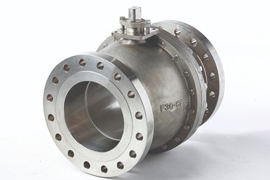
API 6D trunnion ball valves.

API 6D trunnion ball valves.

The heritage of ball valves is much shorter compared to gate, globe and check valve designs. Although the first ball valve patent was issued in 1871, it would take another 85 years for ball valves to become a commercial success. The discovery of polytetrafluoroethylene (PTFE, or “Teflon”) during the process design for manufacturing the atomic bomb in World War II, would be the catalyst that started the ball valve industry rolling. Ball valves come in all materials from brass to carbon steel and stainless steel to zirconium.

There are two basic types: floating ball and trunnion ball. These two designs allow for the construction of effective ball valves from ¼” through 60” and larger. Generally, the floating design is used for smaller and lower-pressure valves, while the trunnion type is used for larger and higher-pressure valve applications.

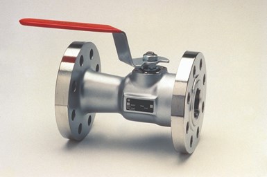
Floating ball valve.

Floating ball valve.

The reason for the two types of ball valves has to do with the way they seal and how the fluid force is distributed from the line flow to the ball and then to the seat. In the floating ball design, the ball is riding snugly between two seats, one upstream and one downstream. The force of the fluid acts on the ball to push it into the seat located in the downstream valve body. Since the ball covers the entire flow bore, all the force in the stream is pushing against the ball to force it into the seat. If the ball gets to be too large and the pressure too high, the force will be so great on the seat that the valve cannot be operated because the operating torque would be too high.

Floating ball valves come in a variety of body styles, although the two-piece, end entry type is the most popular. Other body styles include three-piece and top entry. Floating ball valves are manufactured in sizes up to 24” and class 300, but the practical realm of the floating ball valve is generally much lower—up to about 12”.

Although ball valves are designed primarily to be on/off or “block” valves, the addition of partial ball and V-port ball designs can make them good choices for control-type applications.

RESILIENT SEATS

The smaller floating ball valves are found in many different applications from household plumbing to those containing the harshest chemicals. The most popular seating material in these valves is some form of thermoplastic, such as PTFE. PTFE seats work very well because they are soft enough to seal well on to the polished metallic ball, yet firm enough not to blow out of the valve. The two primary concerns with these soft-seated valves are that they are susceptible to scratching (and potential leakage) and are limited to temperatures below the melting point of the thermoplastic seats—somewhere around 450oF (232oC) depending on the exact seat material.

A ball valve

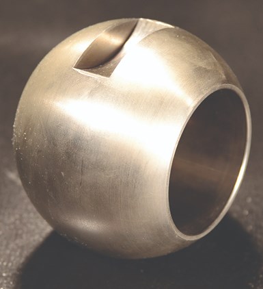
A ball valve “ball.”

A feature of many resilient-seated floating ball valves is the ability to moderately seal in the event of a fire that causes the primary seats to melt. This is called a fire-safe design; it features a seat pocket that not only holds the resilient seat in place, but also provides a metallic seating surface that can provide a partial seal as it contacts the ball. The fire-safe design is confirmed by testing the valve in accordance with the American Petroleum Institute (API) 607 or 6FA fire-testing standards.

TRUNNION DESIGN

When larger sizes and higher-pressure ball valves are needed, the design shifts to the trunnion style. The trunnion differs from the floating style in that the trunnion ball is held in the body via a trunnion (short, attached stem) in the bottom and by the stem at the top. Since the ball cannot “float” into the seat to attain positive closure, the seat must float to the ball instead. The trunnion seat is designed so that the seat is energized by the upstream pressure and is forced into the ball to seal. Because the ball is held securely in place, except for its 90o rotation, the extraordinary fluid force and pressure does not jam the ball into the seat. Instead, the force acts only on a small area on the periphery of the floating seat.

The trunnion ball valve is the brawny big brother to the floating ball valve and as such it gets to handle the big jobs—high pressures and large pipe diameters. By far the most popular use of trunnion ball valves is for pipeline service. These valves are especially popular in natural gas pipelines in diameters up to 60” and pressures up to class 600. Trunnion ball valves can also be used in higher pressures if required. By using trunnion designs the torque required to open and close the valve is lower, so smaller actuators can be used.

End-entry design.

End-entry design.

The trunnion design also lends itself well to double block and bleed service since both the upstream and downstream seats float independently and most designs also feature a body or drain connection. Trunnion designs often employ seat lubrication ports where a lubricant can be injected around the seat to assist in closure efficacy.

METAL-SEATED DESIGNS

The biggest advancement in ball valve technology over the past 30 years or so is the metal-seated ball valve. While the idea of metal seats and a metal ball are not new—in fact, the first ball patent in 1871 featured a brass ball and brass seats—the design needed advancements in coating technology to really be perfected.

The metal-seated ball valve design has enabled ball valves to take a big chunk out of the market share dominated for decades by the venerable gate valve. The metal-seated, specialty-coated ball closes tightly against a set of precision coated and lapped seats, providing zero-leakage, if the hardened seating surfaces are not scratched by debris in the line.

BALL VALVE STANDARDS

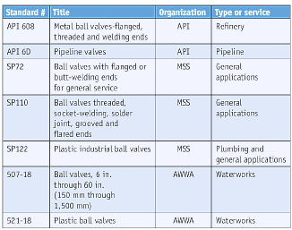
The are several standards that apply to ball valves. The following table lists the most common ball valve design documents:

Ball valves have made huge inroads in replacing other valve types over the past 40 years. The cost to manufacture the smaller sizes has dropped greatly as well, making them even more competitive. The advances in coatings and metal-seated ball valve technology have created very robust designs that have resulted in an attractive total cost of ownership.

Table 1. Common ball valve standards.

Table 1. Common ball valve standards.

While the overall industrial valve segment is still dominated by gate and globe, linear-valve designs, the relatively young ball valve is steadily making up ground, and the metal-seated types have become the preferred valve design for severe-service applications around the world.

In need of assistance in selecting a ball valve ? The experts at STV VAlVE have the knowledge and experience to help. Shop stvvalve.com today!
,

What is a Y Strainer and How to Work

A Y strainer, sometimes referred to as a y strainer, is designed to mechanically remove solids and other particles from fluids. They are an essential component in numerous fluid control applications to ensure no down-stream component is affected by particles within the fluid. In this article we will review their design, use cases, how to size the mesh filter, materials, and how to clean them.

Table of Contents

Y Strainer Design

As its name implies, a Y strainer is shaped like a “Y” and is used to filter, or strain, out particulates from steam, gas or liquid. This mechanical straining process is made possible via a filter element comprised of mesh, perforated metal, or a wedge wire straining element. The most common kind of straining element is a wire mesh. Some also include “blow-off valves” that make the cleaning process easier in applications with more substantial dirt blowing. The strainer itself has a compact, Y shaped design. The Y shape has better flow characteristics then for example a T shaped strainer, because the fluid flows through the filter with less change of direction.

Why Use a Y Strainer?

In general, Y strainers are critical anywhere clean fluids are required. While clean fluids can help maximize the reliability and lifespan of any mechanical system, theyre especially important with solenoid valves. This is because solenoid valves are very sensitive to dirt and will only function properly with clean liquids or air. If any solids enter the stream, it can disrupt and even damage the entire system. Therefore, a Y strainer is a great complimentary component. In addition to protecting the performance of solenoid valves, they also help safeguard other types of mechanical equipment, including:

  • Pumps
  • Turbines
  • Spray nozzles
  • Heat exchangers
  • Condensers
  • Steam traps
  • Meters

A simple Y strainer can keep these components, which are some of the most valuable and expensive parts of the pipeline, protected from the presences of pipe scale, rust, sediment or any other kind of extraneous debris. Y strainers are available in a myriad of designs (and connection types) that can accommodate any industry or application.

Sizing Your Mesh Filter for a Y strainer

Of course, the Y strainer wouldnt be able to do its job without the mesh filter that is properly sized. To find the strainer thats perfect for your project or job, it’s important to understand the basics of mesh and screen sizing. There are two terms used to describe the size of the openings in the strainer through which debris passes. One is micron and the other is mesh size. Though these are two different measurements, they describe the same thing.

What is a Micron?

Standing for micrometer, a micron is a unit of length thats used to measure tiny particles. For scale, a micrometer is one thousandth of a millimeter or about one 25-thousandths of an inch.

What is Mesh Size?

A strainers mesh size indicates how many openings there are in the mesh across one linear inch. Screens are labeled by this size, so a 14-mesh screen means youll find 14 openings across one inch. So, a 140-mesh screen means that there are 140 openings per inch. The more openings per inch, the smaller the particles that can pass through. The ratings can range from a size 3 mesh screen with 6,730 microns to a size 400 mesh screen with 37 microns.

Micron-to-Mesh Conversion Chart

The chart below is a handy resource to help you convert from mesh to micron (or vice-versa).


Mesh Screen Mesh Size Microns
2000 10 0.0787
1680 12 0.0661
1410 14 0.0555
1190 16 0.0469
1000 18 0.0394
841 20 0.0331
707 25 0.028
595 30 0.0232
500 35 0.0197
420 40 0.0165
354 45 0.0138
297 50 0.0117
250 60 0.0098
210 70 0.0083
177 80 0.007
149 100 0.0059
125 120 0.0049
105 140 0.0041
88 170 0.0035
74 200 0.0029
63 230 0.0024
53 270 0.0021
44 325 0.0017
37 400 0.0015

In addition, it can be helpful to see an example of mesh sizes based on certain particles, as shown below:


Mesh Size Microns Example of particle size
14 0.05551400
28 0.028700 Beach Sand
60 0.0098250 Fine Sand
100 0.0059150
200 0.002974 Portland Cement
325 0.001744 Silt
400 0.001537 Plant Pollen

Determining Your Proper Filter Size

To select the right filter size for your application, youll need to consider the size, scope, and environment of the project. Some of the most important factors to gauge include:

  • The type of pipe system youre using.
  • The kind of material that makes up the system.
  • The size of the debris or particles you want to capture.
  • The systems pressure and temperature levels.

Its important to take the time to size your mesh filter correctly. Sizing it too small or too large can negatively affect your system as a whole. If your filter is too small (with a lot of openings), there will be a greater pressure drop from inlet to outlet. Additionally, removing too much debris can result in additional maintenance due to a collection of debris which can also cause an increased pressure drop. If it is too large (allowing large particles through), this can affect the performance and life span of your downstream equipment.

Housing Material Options

Now that weve covered why Y strainers are important and what theyre used for, lets discuss a few of the different kinds of Y strainers available. These strainers are available in a wide variety of material types and fall into different classes defined by the American National Standards Institute (ANSI). First, lets take a look at the different material housing options available, which include:

  • Brass
  • Stainless steel
  • (Carbon) Steel
  • Bronze
  • Cast iron
  • Ductile iron
  • Plastics

Note that these different kinds of housing materials are designed to fit certain environments and media.

Seal Material Options

The seal on a Y strainer helps ensure its functionality and extend its service life. Some of the common options are:

PTFE Seal

This is one of the most common types of seal materials. In addition to holding fast in even the most aggressive environments, these are also ideal for low and high temperatures.

Fluoro Rubber Seal

When youre shopping for a Y strainer, you might come across a few different kinds of seals that sound similar. These include:

  • FKM
  • FPM
  • Viton®

These individual designations all describe the same base material: Fluoro rubber. Why the different names? In short, the ASTM abbreviates the material as FKM while the DIN/ISO abbreviates the entire fluoroelastomer category as FPM. And, DuPont Performance Elastomers trademarked the material as Viton®.

EPDM Seal

Standing for ethylene-propylene-diene-monomer, EPDM is an elastomer similar to Fluoro rubber. However, it features a different chemical resistance and temperature range compared to FPM.

How to Clean Your Y Strainer

How often youll need to clean your component depends on the process youre running, mesh size, and the materials youre filtering. Remember to close off all valve connections on both sides of the Y strainer to relieve pressure as you start to clean. From there, you can loosen and remove the plug at the end of the filter leg to access the filter. Empty out all of the collected material and debris, clean the filter and replace.

Y Strainer Selection Criteria

There are different kinds of Y strainers on the market designed to meet various industry needs. As you research which one is best for you, keep the following criteria in mind:

  • Port size
  • The temperature in your environment
  • The pressure level in your environment
  • Preferred installation orientation
  • The kind of debris you need to strain
  • Ease of maintenance

There is no one-size-fits-all Y strainer that meets every need. Thats why its important to understand your application requirements before moving forward.

Typical Y Strainer Applications

A Y strainer is most valuable in an environment that requires constant protection from debris and contamination. Lets take a look at a few of the most common applications that require their use.

Steam Applications

These strainers are a go-to resource in most steam applications, as its shape is built to handle the high pressure that exists in these environments.

Liquid Applications

Liquid applications tend to become infiltrated by sand and gravel, and Y strainers can help keep those particles out to ensure the liquid stays clean. Especially when they work in tandem with other water-handling applications, these strainers can protect important (and expensive) equipment from damage, corrosion or clogs that could result from such contamination.

Natural Gas and Air Applications

Natural gas and air applications tend to have a low operating pressure, so proper sizing to reduce a pressure drop from inlet to outlet is important.

Frequently Asked Questions

Its easy to become overwhelmed when youre researching the best Y filter for your needs. To that end, lets take a look at a few common inquiries and how to solve them.

How Should I Install My Strainer?

Y strainers have an arrow from inlet to outlet. It is important to install them in this orientation for proper filtration.

What Kind of End Connections are Available?

Depending on your needs, Y filters can include a variety of end connections, including flanged, threaded and welded. You can also find special flanges, such as ring joints.

What Kind of Housing Material Should I Choose?

Depending on your environment and media, a different Y strainer housing material and seal material should be selected. Ensure you know the chemical resistance of them to select the proper one.

Are Y Strainers Affordable?

Yes! This type of strainer is also an affordable alternative to other types of strainers, made even more economical as you scale down in size. Considering they protect more expensive components, they are a good investment.

Should I Choose on My Own?

This article should help you select the proper Y strainer for your application. However, feel free to contact our technical support with any questions.

,

Ball Valves vs Globe Valves,Which Valve is Best for You?

There are many different types of valves available for different applications. With so much choice it can be difficult to decide which valve is most suitable for your application. In this article, STV Supplies explores the merits of ball valves versus globe valves.


WHAT IS THE MAIN DIFFERENCE BETWEEN BALL AND GLOBE VALVES?

The main difference between ball and globe valves is the way they close. Ball valves have a stem and ball, which turns horizontally, and are commonly referred to as “rotational” valves. Whereas, globe valves have a stem and plug, which strokes linearly, and gives them their other name of “stroke” valves. Ball valves are best suited to applications requiring on/off control without pressure drop. While globe valves excel at regulating flow.

HOW DOES A BALL VALVE WORK?

Ball valves are designed with a ball inside the valve. A ball valve is a form of quarter-turn valve which uses a hollow, perforated and pivoting ball (called a “floating ball”) to control flow through it. It is open when the ball’s hole is in line with the flow and closed when it is pivoted 90-degrees by the valve handle. The handle lies flat in alignment with the flow when open, and is perpendicular to it when closed, making for easy visual confirmation of the valve’s status.

HOW DOES A GLOBE VALVE WORK?

Globe valves were for many years the industry standard in control valves. They are named for their spherical body shape, with the two halves of the body being separated by an internal baffle. This has an opening that forms a seat onto which a movable plug (or disc) can be screwed in to close the valve. Typically, automated globe valves use smooth stems rather than threaded and are opened and closed by an actuator assembly.

WHICH IS BETTER: A BALL VALVE OR GLOBE VALVE?

Ball valves are durable, performing well after many cycles, and reliable, closing securely even after long periods of disuse. These qualities make them an excellent choice for shutoff applications, where they are often preferred to gates and globe valves. On the flip side, ball valves do lack the fine control in throttling applications offered by globe valves.

STV SUPPLIES STOCKS BALL AND GLOBE VALVES


STV stock a wide range of ball valves, from quarter-inch to six-inch at our works in Bishopbriggs. From general purpose two-piece ball valves, v-ball control valves, hygienic valves, to heavy duty ball valves for steam; we have a variety of sizes, end connections and materials to suit many applications. We also stock globe valves up to six-inch in size, and can supply many size and material variants on a next-day basis.

,

how to select Gate Valve

Knowing the right kind of gate valve to select depends greatly on how you are planning to use it in your piping system. A professional’s advice and guidance can help whittle down the choices and recommend which one will work best in your precise setup.

There are two basic types of gate valves that can be purchased and installed as part of the plumbing system of a structure. These two types depend on the manner in which the disk is designed in the actual gate valve. As mentioned in the article parts of a gate valve, the gate valve disk is basically the gate that can seal shut when the valve is closed, meaning no water flow is possible, and can open when the valve is opened, allowing water pressure to pass through.

The two basic types of gate valves are:

1. Parallel Gate Valve


The parallel gate valve is used in valves that have parallel valve seats. The two halves of the parallel disk can either be thrust together or spread apart and there is often a spring-like mechanism that assists in the proper sealing of the disks to the seats. There is a variety of designs that use the parallel gate valve but the bottom line for each design is to make sure that there is optimum sealing that occurs between the disks and the seats.

2. Wedge Gate Valve


The wedge gate valve is separated into three categories:

  • Solid Wedge: The solid wedge gate valve is considered to be the most commonly used disk and is known for the simplicity in its design that belies its strength. The solid wedge gate valve functions well in any position it is placed in and can handle almost any kind of fluid.
  • Flexible Wedge: The flexible wedge gate valve is a singular disk whose perimeter has a cut around it in order to be able to fit better in the valve seats. The cut depends on the design of the valve seats and the flexible wedge gate valve works best with steam systems since heat can cause expansion and cold can cause contraction, making it necessary for more flexibility to occur within the disk.
  • Split Wedge: The split wedge gate valve has a ball and socket design that are able to self-adjust and self-align to the valve seats’ surfaces. This makes it possible for half the disk to adjust and align itself if the other half is unable to do so due to something being lodged that makes it impossible for it fit snugly into the valve seat. The split wedge gate valve is appropriate for systems that handle non-condensing gases and liquids.

Knowing the right kind of gate valve to select depends greatly on how you are planning to use it in your piping system.One particular type of design may work specifically for plumbing purposes in a home while another type of design may work better in an industrial setting. This is why it is important to have the correct information on each type of gate valve and whether they will meet your specific requirements and needs. A professional’s advice and guidance can help whittle down the choices and recommend which one will work best in your precise setup.

,

how to maintain a gate valve

Like other mechanical products, valves also need maintenance. This work well, can extend the service life of the gate valve, the following will introduce the maintenance of the Gate valve.

1. Gate Valve storage and maintenance

The purpose of storage and maintenance is not to damage the valve or reduce the quality. In fact, improper storage is one of the important reasons for valve damage.
The Gate valves should be kept in good order. The small valves should be placed on the shelf. The large valves can be arranged in order on the ground of the warehouse. They should not be stacked disorderly. The flange connection surface should not contact the ground. This is not only for the sake of beauty, but also to protect the valve from damage.
Due to improper storage and handling, broken handwheel, crooked valve stem, loose nut between handwheel and valve stem, etc., these unnecessary losses should be avoided.
Asbestos packing should be taken out for valves not to be used for a short time to avoid electrochemical corrosion and damage of valve stem.
Check the valve just entering the warehouse. If there is rain or dirt in the process of transportation, wipe it clean and then store it.
The inlet and outlet of the valve should be sealed with wax paper or plastic sheet to prevent dirt.
The valve surface that can rust in the atmosphere should be coated with antirust oil for protection.
The outdoor Gate valves must be covered with rain proof and dust-proof materials such as linoleum or tarpaulin. The warehouse where the Gate valves are stored should be kept clean and dry.

2. Gate valves operation and maintenance

The purpose of operation and maintenance is to extend the service life of the valve and ensure the reliability of opening and closing.
Stem thread, often with the stem nut friction, to apply a little yellow dry oil, molybdenum disulfide or graphite powder, lubrication.
Do not often open and close the valve, but also regularly turn the hand wheel, add lubricant to the stem thread to prevent seizure.
For outdoor valves, theGate valves stem shall be protected from rain, snow, dust and rust.
If the Gate valves is mechanical, add lubricating oil to the gearbox on time.
Always keep the valve clean.
Always check and maintain the integrity of other parts of the valve. If the fixing nut of the hand wheel falls off, it should be matched and can not be used properly, otherwise it will grind the square on the upper part of the valve stem, gradually lose the reliability of matching, and even can not start.
Do not rely on the Gate valves to support other heavy objects, do not stand on the Gate valves.
The valve stem, especially the thread part, should be wiped frequently, and the lubricant that has been contaminated by dust should be replaced with a new one, because the dust contains hard debris, which is easy to wear the thread and the surface of the valve stem, affecting the service life.

3. Maintenance of valve packing

The packing is directly related to the key seal of valve leakage when opening and closing. If the packing fails, causing leakage, the valve will be equivalent to failure, especially the valve of urea pipeline, because of its high temperature, corrosion and easy aging of packing. Strengthening maintenance can prolong the life of packing.
When the valve leaves the factory, in order to ensure the elasticity of the packing, it is generally subject to the static pressure test without leakage. After the valve is installed into the pipeline, due to the temperature and other factors, the leakage may occur. At this time, the nuts on both sides of the packing gland should be tightened in time. As long as there is no leakage, the leakage can occur again in the future. Do not tighten it once, so as to avoid the loss of elasticity and sealing performance of the packing.
Some valve packing is filled with molybdenum disulfide grease. When it is used for several months, the corresponding grease should be added in time. When it is found that the packing needs to be supplemented, the corresponding packing should be added in time to ensure its sealing performance.


4. Maintenance of valve transmission parts

In the process of valve opening and closing, the original lubricating oil will be continuously lost. Coupled with the effect of temperature, corrosion and other factors, the lubricating oil will continue to dry up. Therefore, the transmission parts of the valve should be checked frequently, and the lack of oil should be added in time, so as to prevent the increase of wear due to the lack of lubricant, resulting in inflexibility of transmission or failure of case


5. Maintenance of valve during grease injection

When the Gate valves is greased, the amount of grease is often ignored. After the grease gun is filled with oil, the operator selects the valve and grease connection mode to carry out the grease injection operation. There are two situations: on the one hand, the amount of grease injection is less, and the sealing surface is worn faster due to the lack of lubricant. On the other hand, excessive fat injection causes waste. The reason is that there is no accurate calculation for the sealing capacity of different valves according to the valve type. The sealing capacity can be calculated according to the valve size and type, and then a reasonable amount of grease can be injected.
When the valve is greased, the pressure problem is often ignored. During the operation of fat injection, the pressure of fat injection changed regularly from peak to valley. If the pressure is too low, the seal leaks or fails, if the pressure is too high, the grease injection port is blocked, the grease in the seal is hardened, or the seal ring is locked with the valve ball and valve plate. Usually, when the grease injection pressure is too low, the injected grease flows into the bottom of the valve chamber, which usually occurs in small gate valves. On the one hand, check the grease nozzle, if the grease hole is blocked, judge the situation and replace it; On the other hand, it is the hardening of grease. It is necessary to use cleaning fluid to soften the failed sealing grease repeatedly and inject new grease for replacement. In addition, seal type and seal material also affect the grease injection pressure. Different seal forms have different grease injection pressure. Generally, the grease injection pressure of hard seal is higher than that of soft seal.

When greasing the valve, pay attention to the problem that the valve is in the on / off position. Ball valve maintenance is generally in the open state, special circumstances choose to close maintenance. Other valves can not be treated as open. The gate valve must be closed during maintenance to ensure that the grease fills the sealing groove along the sealing ring. If it is open, the grease will directly fall into the flow channel or valve cavity, causing waste.

When the Gate valves is greased, the effect of greasing is often ignored. During the operation, the pressure, amount and switch position were normal. However, in order to ensure the effect of valve greasing, sometimes it is necessary to open or close the valve, check the lubrication effect, and confirm that the surface of valve ball or ram is evenly lubricated.
Attention should be paid to the blowdown of valve body and the pressure relief of screw plug during grease injection. After the pressure test of the valve, the gas and water in the valve chamber of the sealing chamber will be increased due to the rise of the ambient temperature, and the blowdown and pressure relief should be carried out before the grease injection, so as to facilitate the smooth progress of the grease injection. The air and water in the sealing cavity are fully replaced after grease injection. The pressure of the valve chamber is released in time, which ensures the safety of the valve. After grease injection, the drain and pressure relief plugs must be tightened to prevent accidents.
When injecting fat, pay attention to the problem of even fat. During normal fat injection, the nearest fat hole to the fat injection port first gets fat, then goes to the low point, finally to the high point, and then gets fat one by one. If not in accordance with the law or not out of fat, prove the existence of blockage, timely clearing treatment.
When greasing, the valve diameter and sealing ring seat should also be observed. For example, for ball valve, if there is open position interference, the open position limiter can be adjusted inward, and it can be locked after confirming that the diameter is straight. The adjustment of the limit should not only pursue the position of the opening or closing side, but should be considered as a whole. If the opening position is flush and the closing position is not in place, the valve will not be closed tightly. In the same way, the corresponding adjustment of the opening position should also be considered when adjusting the closing position. Ensure right angle travel of the valve.
After the grease injection, the grease injection port must be sealed. Avoid impurities entering or lipid oxidation at the grease injection port. The cover shall be coated with anti rust grease to avoid rusting. So that it can be applied in the next operation.

When greasing, we should also consider the specific problems in the future oil sequential transportation. In view of the different quality of diesel and gasoline, the scouring and decomposition capacity of gasoline should be considered. In the later valve operation, in case of gasoline section operation, timely add grease to prevent wear.
When greasing, do not ignore the greasing of the valve stem. There is sliding sleeve or packing on the valve shaft, which also needs to be lubricated to reduce the friction resistance during operation. If the lubrication can not be ensured, the torque will be increased during electric operation, and the worn parts will be worn, and the switch will be laborious during manual operation.
Some ball valves are marked with arrows on the valve body. If there is no English fiow handwriting attached, it is the direction of action of the sealing seat, not as a reference for the flow direction of the medium. The direction of self discharge of the valve is opposite. In general, double seat sealed ball valve has two-way flow direction.
During valve maintenance, attention should also be paid to the problem of water inflow in the electric actuator and its transmission mechanism. Especially in rainy season. One is to rust the transmission mechanism or shaft sleeve, the other is to freeze in winter. When the electric valve is operated, the torque is too large, and the transmission parts will be damaged, which will make the motor no-load or over torque protection jump off, and the electric operation cannot be realized. The transmission parts are damaged, and manual operation cannot be carried out. After the over torque protection action, manual operation is also unable to switch, if forced operation, the internal alloy parts will be damaged.
Valve maintenance should be treated with a scientific attitude in order to achieve the desired effect and application purpose. In order to make the production run normally, reduce the shutdown and increase the economic benefits, we must do these three things well in the aspect of valves

Correct selection of valves is the foundation.
Correct use of the valve is the key.
Correct maintenance is the guarantee.

,

Gate valve Overview

Overview of gate valve standard: the opening and closing part of gate valve is gate.

The movement direction of the ram is perpendicular to the direction of the fluid.

The gate valve can only be fully opened and fully closed, and cannot be adjusted or throttled. The gate has two sealing surfaces. The two sealing surfaces of commonly used gate valves are wedge-shaped, and the wedge angle varies with the valve parameters. Wedge gate valve gate can be made into a whole, known as the rigid gate; It can also be made into a ram that can produce a small amount of deformation, so as to improve its processability and make up for the deviation of sealing surface angle in the processing process. This kind of ram is called elastic ram.
Working principle of gate valve: when the gate valve is closed, the sealing surface of flange gate valve can only be sealed by medium pressure, that is, the sealing surface of gate valve is pressed to the valve seat on the other side by medium pressure to ensure the sealing of secret cover, which is self sealing. Most gate valves use forced sealing, that is, when the valve is closed, the gate must be pressed to the seat by external force to ensure the sealing surface. Gate valve gate and stem linear movement, lifting stem gate valve (also known as rising stem gate valve). Generally, there is a trapezoidal thread on the lifting rod, which passes through the nut on the top of the valve and the guide groove on the valve body. The rotary motion becomes linear motion, that is, the operating torque becomes the operating thrust.

When the gate valve is opened:
When the lifting height of the flange gate valve is equal to 1:1 of the valve diameter, the fluid passage will be completely unobstructed, but this position cannot be monitored during operation. In practical use, the apex of the stem is used as a mark, that is, the position where it cannot be opened, as its fully open position. In order to consider the locking phenomenon caused by temperature change, it is usually opened to the top position, and then returned to 1 / 2-1 circle as the position of full open gate valve. Therefore, the full open position of the valve is determined by the position (i.e. stroke) of the ram. In some gate valves, the stem nut is installed on the gate valve, and the handwheel rotation drives the stem to rotate, so as to lift the gate. This kind of valve is called rotary stem gate valve or Non rising stem gate valve.

Gate valve type: according to the configuration of sealing surface, flange gate valve can be divided into wedge gate valve and parallel gate valve. Wedge gate valve can be further divided into: single gate type, double gate plate type and elastic gate type; Parallel gate valve can be divided into single gate plate and double gate plate. According to the thread position of the stem, it can be divided into two types: rising stem gate valve and Non rising stem gate valve.

Gate valve structure features:

1. Gate valve fluid resistance is small, sealing surface is less media scrubbing and corrosion.

2. The workload of opening and closing is saved.

3. The flow direction of the medium is not limited, it will not interfere with the flow, and it will not reduce the pressure.

4. Simple shape, short structure length, good manufacturing process and wide application range.

Application scope of gate valve: gate valve is widely used in domestic steel plant, petroleum, chemical, natural gas, boiler, paper making, textile, medicine, food, transportation, water supply and drainage, energy, polysilicon, electric power and other industrial pipelines for medium cutting and circulation. Flange gate valve is suitable for pipes with nominal pressure of pn1.6 ~ 6.4Mpa and working temperature of – 29 ~ 600 ℃. It can cut off or connect pipeline medium without adjustment and throttling. The applicable medium of gate valve is water, oil, steam, acid medium, etc.