
Ball Valve Basics
Welcome to the first in a series of Valve Basics articles, each focused on a major product type and written especially for newcomers to the industries that use and make valves and related products.
Ball valves may not bounce very well but they work great at regulating flow. The popular valve is named for its round ball that sits in the interior of the valve body and pushes into a seat to control or provide on/off functions in fluid pipelines.
The heritage of ball valves is much shorter compared to gate, globe and check valve designs. Although the first ball valve patent was issued in 1871, it would take another 85 years for ball valves to become a commercial success. The discovery of polytetrafluoroethylene (PTFE, or “Teflon”) during the process design for manufacturing the atomic bomb in World War II, would be the catalyst that started the ball valve industry rolling. Ball valves come in all materials from brass to carbon steel and stainless steel to zirconium.
There are two basic types: floating ball and trunnion ball. These two designs allow for the construction of effective ball valves from ¼” through 60” and larger. Generally, the floating design is used for smaller and lower-pressure valves, while the trunnion type is used for larger and higher-pressure valve applications.
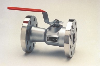
Floating ball valve.
The reason for the two types of ball valves has to do with the way they seal and how the fluid force is distributed from the line flow to the ball and then to the seat. In the floating ball design, the ball is riding snugly between two seats, one upstream and one downstream. The force of the fluid acts on the ball to push it into the seat located in the downstream valve body. Since the ball covers the entire flow bore, all the force in the stream is pushing against the ball to force it into the seat. If the ball gets to be too large and the pressure too high, the force will be so great on the seat that the valve cannot be operated because the operating torque would be too high.
Floating ball valves come in a variety of body styles, although the two-piece, end entry type is the most popular. Other body styles include three-piece and top entry. Floating ball valves are manufactured in sizes up to 24” and class 300, but the practical realm of the floating ball valve is generally much lower—up to about 12”.
Although ball valves are designed primarily to be on/off or “block” valves, the addition of partial ball and V-port ball designs can make them good choices for control-type applications.
RESILIENT SEATS
The smaller floating ball valves are found in many different applications from household plumbing to those containing the harshest chemicals. The most popular seating material in these valves is some form of thermoplastic, such as PTFE. PTFE seats work very well because they are soft enough to seal well on to the polished metallic ball, yet firm enough not to blow out of the valve. The two primary concerns with these soft-seated valves are that they are susceptible to scratching (and potential leakage) and are limited to temperatures below the melting point of the thermoplastic seats—somewhere around 450oF (232oC) depending on the exact seat material.
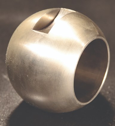
A ball valve “ball.”
A feature of many resilient-seated floating ball valves is the ability to moderately seal in the event of a fire that causes the primary seats to melt. This is called a fire-safe design; it features a seat pocket that not only holds the resilient seat in place, but also provides a metallic seating surface that can provide a partial seal as it contacts the ball. The fire-safe design is confirmed by testing the valve in accordance with the American Petroleum Institute (API) 607 or 6FA fire-testing standards.
TRUNNION DESIGN
When larger sizes and higher-pressure ball valves are needed, the design shifts to the trunnion style. The trunnion differs from the floating style in that the trunnion ball is held in the body via a trunnion (short, attached stem) in the bottom and by the stem at the top. Since the ball cannot “float” into the seat to attain positive closure, the seat must float to the ball instead. The trunnion seat is designed so that the seat is energized by the upstream pressure and is forced into the ball to seal. Because the ball is held securely in place, except for its 90o rotation, the extraordinary fluid force and pressure does not jam the ball into the seat. Instead, the force acts only on a small area on the periphery of the floating seat.
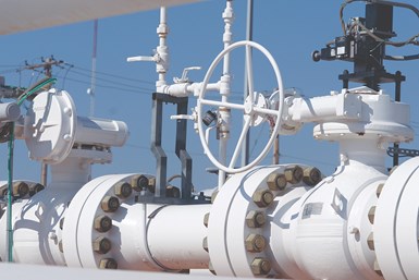
The trunnion ball valve is the brawny big brother to the floating ball valve and as such it gets to handle the big jobs—high pressures and large pipe diameters. By far the most popular use of trunnion ball valves is for pipeline service. These valves are especially popular in natural gas pipelines in diameters up to 60” and pressures up to class 600. Trunnion ball valves can also be used in higher pressures if required. By using trunnion designs the torque required to open and close the valve is lower, so smaller actuators can be used.
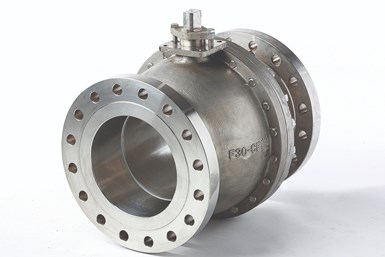
End-entry design.
The trunnion design also lends itself well to double block and bleed service since both the upstream and downstream seats float independently and most designs also feature a body or drain connection. Trunnion designs often employ seat lubrication ports where a lubricant can be injected around the seat to assist in closure efficacy.
METAL-SEATED DESIGNS
The biggest advancement in ball valve technology over the past 30 years or so is the metal-seated ball valve. While the idea of metal seats and a metal ball are not new—in fact, the first ball patent in 1871 featured a brass ball and brass seats—the design needed advancements in coating technology to really be perfected.
The metal-seated ball valve design has enabled ball valves to take a big chunk out of the market share dominated for decades by the venerable gate valve. The metal-seated, specialty-coated ball closes tightly against a set of precision coated and lapped seats, providing zero-leakage, if the hardened seating surfaces are not scratched by debris in the line.
BALL VALVE STANDARDS
The are several standards that apply to ball valves. The following table lists the most common ball valve design documents:
Ball valves have made huge inroads in replacing other valve types over the past 40 years. The cost to manufacture the smaller sizes has dropped greatly as well, making them even more competitive. The advances in coatings and metal-seated ball valve technology have created very robust designs that have resulted in an attractive total cost of ownership.
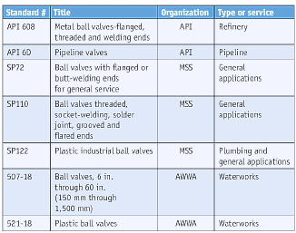
Table 1. Common ball valve standards.
While the overall industrial valve segment is still dominated by gate and globe, linear-valve designs, the relatively young ball valve is steadily making up ground, and the metal-seated types have become the preferred valve design for severe-service applications around the world.

 Figure 2: Gate valve components
 Figure 3: Bolted bonnet
  Figure 4: Wedge gate valve vs parallel gate valve
 Figure 5: Slab gate valve
 Figure 6: Expanding gate functioning
 Figure 7: Mechanism of rising stem gate valves vs non-rising stem gate valves